
User's Manual Part 1
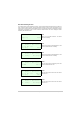
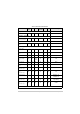
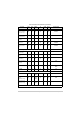
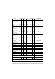


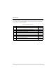
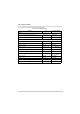
Table Of Contents
- Health and Safety
- Customer Support
- Abbreviations
- Overview
- Specification
- Operation
- Overview
- T6T VHF Amplifier
- Drive Assembly
- Setting Up and Operation
- Normal Operation
- Using the Scroll/Select Switch
- Screen Protocol
- Menu System
- Menu Lock Screen
- Control Screen
- Notes for Setting Up the Transmitter
- Changing the Transmitter’s Operating Frequency
- To Store and Recall Frequency Channels
- To Initiate a BIT Test
- Standby Mode
- Settings
- AM-Voice Settings Procedure
- AM-MSK Mode Settings Procedure
- Mode 2 Settings Screen
- Mode 3 Settings Screen
- Polarities Screen AM-Voice and AM-MSK
- Mode 2 and Mode 3 Polarity Settings
- AM-Voice and AM-MSK BIT Screen
- Mode 2 and Mode 3 BIT Screen
- Software Configuration Screens
- Band Edges
- BIT Status Warning Screens
- Installation
- Warnings and Cautions
- Introduction
- Installing the Transmitter

T6T 300 Watt VHF Transmitter Page 65 Operation
Set PTT reference
voltage
(AM modes only)
✔✔
View
state
✗✗✗ +14 V
Set PTT output
polarity
(AM modes only)
✔✔
View
state
✗✗✗
STD
Set fast PTT
antenna change-
over output polarity
(AM modes only)
✔✔
View
state
✗✗✗ STD
Set antenna
change-over output
polarity
(AM modes only)
✔✔
View
state
✗✗✗
STD
Set external VSWR
input polarity
(All modes)
✔✔
View
state
✗✗✗
STD
Set inhibit input
polarity
(AM modes only)
✔✔
View
state
✗✗✗
STD
BIT interruptive test
input polarity
(AM modes only)
✔✔
View
state
✗✗✗
STD (active low)
E-BIT input polarity
(All modes)
✔✔
View
state
✗✗✗
STD (active low)
Band Edges
Set band edges
✔✔ ✗ ✗ ✗✗118.000 and 136.975 MHz
Reference Frequency
Adjust transmitter’s
reference frequency
✔✔ ✗ ✗ ✗✗
-
LCD Backlight
Adjust LCD
backlight
✔✔ ✗ ✗ ✗✗
30 s
BIT
Initiate BIT
interruptive test
✔✔✔ ✔ ✗✗
-
Continued ...
Table 12 Functions and Parameters (Continued)
Function Front
Panel
VFP MARC T6
Controller
T1/E1 HDLC Default Setting