
User's Manual Part 1
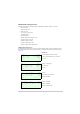
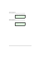
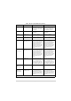
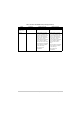
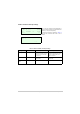
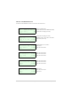
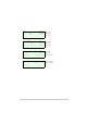
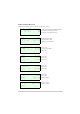
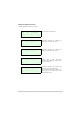
Table Of Contents
- Health and Safety
- Customer Support
- Abbreviations
- Overview
- Specification
- Operation
- Overview
- T6T VHF Amplifier
- Drive Assembly
- Setting Up and Operation
- Normal Operation
- Using the Scroll/Select Switch
- Screen Protocol
- Menu System
- Menu Lock Screen
- Control Screen
- Notes for Setting Up the Transmitter
- Changing the Transmitter’s Operating Frequency
- To Store and Recall Frequency Channels
- To Initiate a BIT Test
- Standby Mode
- Settings
- AM-Voice Settings Procedure
- AM-MSK Mode Settings Procedure
- Mode 2 Settings Screen
- Mode 3 Settings Screen
- Polarities Screen AM-Voice and AM-MSK
- Mode 2 and Mode 3 Polarity Settings
- AM-Voice and AM-MSK BIT Screen
- Mode 2 and Mode 3 BIT Screen
- Software Configuration Screens
- Band Edges
- BIT Status Warning Screens
- Installation
- Warnings and Cautions
- Introduction
- Installing the Transmitter

T6T 300 Watt VHF Transmitter Page 56 Operation
Mode 2 and Mode 3 Polarity Settings
Table 10 Mode 2 and Mode 3 Polarity Settings
Signal Connector Polarity set to STD Polarity set to INV
Ready Out Facilities, pin 13 An open collector grounded
output when the radio is ready
to transmit and no BIT faults
are detected.
An open collector high
impedance output when the radio
is ready to transmit and no BIT
faults are detected.
E-BIT In Facilities, pin 2 TTL input. 0 V indicates an
external fault.
TTL input. 5 V indicates an
external fault.
External VSWR
Input
Facilities, pin 4 TTL input. 0 V active. TTL input. 5 V active.
R e a d y O u t S T D
E - B I T I n S T D
E x t V S W R I n S T D
E x i t > >
B a c k
E x i t
< <
Each of the three polarity settings applicable to
Mode 2 and Mode 3 can be set to the default STD
(standard) or INV (inverted) setting.
The signal connections are detailed in Table 10
along with the conditions when STD or INV is
selected.