
User's Manual Part 1
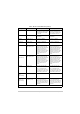
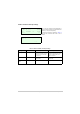

Table Of Contents
- Health and Safety
- Customer Support
- Abbreviations
- Overview
- Specification
- Operation
- Overview
- T6T VHF Amplifier
- Drive Assembly
- Setting Up and Operation
- Normal Operation
- Using the Scroll/Select Switch
- Screen Protocol
- Menu System
- Menu Lock Screen
- Control Screen
- Notes for Setting Up the Transmitter
- Changing the Transmitter’s Operating Frequency
- To Store and Recall Frequency Channels
- To Initiate a BIT Test
- Standby Mode
- Settings
- AM-Voice Settings Procedure
- AM-MSK Mode Settings Procedure
- Mode 2 Settings Screen
- Mode 3 Settings Screen
- Polarities Screen AM-Voice and AM-MSK
- Mode 2 and Mode 3 Polarity Settings
- AM-Voice and AM-MSK BIT Screen
- Mode 2 and Mode 3 BIT Screen
- Software Configuration Screens
- Band Edges
- BIT Status Warning Screens
- Installation
- Warnings and Cautions
- Introduction
- Installing the Transmitter

T6T 300 Watt VHF Transmitter Page 55 Operation
Fast PTT Output
(antenna
change-over)
MARC Audio, pin 3 Open collector NPN transistor
grounding output, 200 mA max,
n/o.
Open collector NPN transistor
grounding output, 200 mA max,
n/c.
PTT Ref - PTT Ref can be set to +14 V,
0 V or -14 V. Maximum input
level ±60 V with respect to PTT
reference. Input will draw no
more than 6 mA, and requires
at least 1 mA to operate.
When the input PTT signal and
the PTT reference differ by
more than 10 V the radio keys.
When the input PTT signal and
the PTT reference are within
1 V, the radio dekeys.
Other conditions are
indeterminable.
PTT Ref can be set to +14 V,
0 V or -14 V. Maximum input
level ±60 V with respect to PTT
reference. Input will draw no
more than 6 mA, and requires
at least 1 mA to operate.
When the input PTT signal and
the PTT reference differ by
more than 10 V the radio
dekeys.
When the input PTT signal and
the PTT reference are within
1 V, the radio keys.
Other conditions are
indeterminable.
Table 9 AM-Voice and AM-MSK Polarity Settings (Continued)
Signal Connector Polarity set to STD Polarity set to INV