
User's Manual Part 1
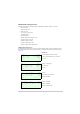

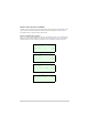
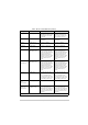
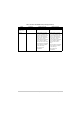
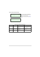
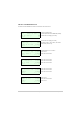
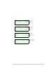
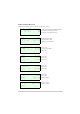
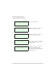
Table Of Contents
- Health and Safety
- Customer Support
- Abbreviations
- Overview
- Specification
- Operation
- Overview
- T6T VHF Amplifier
- Drive Assembly
- Setting Up and Operation
- Normal Operation
- Using the Scroll/Select Switch
- Screen Protocol
- Menu System
- Menu Lock Screen
- Control Screen
- Notes for Setting Up the Transmitter
- Changing the Transmitter’s Operating Frequency
- To Store and Recall Frequency Channels
- To Initiate a BIT Test
- Standby Mode
- Settings
- AM-Voice Settings Procedure
- AM-MSK Mode Settings Procedure
- Mode 2 Settings Screen
- Mode 3 Settings Screen
- Polarities Screen AM-Voice and AM-MSK
- Mode 2 and Mode 3 Polarity Settings
- AM-Voice and AM-MSK BIT Screen
- Mode 2 and Mode 3 BIT Screen
- Software Configuration Screens
- Band Edges
- BIT Status Warning Screens
- Installation
- Warnings and Cautions
- Introduction
- Installing the Transmitter

T6T 300 Watt VHF Transmitter Page 53 Operation
Polarities Screen AM-Voice and AM-MSK
A number of remote indication and control signals can be hardwire connected to the transmitter. These
signals, which can have their polarities set to standard (STD) or inverted (INV), are listed in Table 9.
The Polarities screen is accessed from the Settings screen.
AM-Voice and AM-MSK Polarity Settings
Each of ten polarity settings applicable to AM-Voice and AM-MSK can be set to the default STD
(standard) or INV (inverted) setting. The signal connections are shown in Table 9 along with the
conditions when STD or INV is selected. The settings for the PTT Reference voltage are also given.
R e a d y O u t S T D
E - B I T I n S T D
I n h i b i t I n S T D
E x i t > >
B I T S t a r t I n S T D
P T T R e f + 1 4 V
P T T I n S T D
E x i t > >
P h a n P T T I n S T D
P T T O u t S T D
F a s t P T T O u t S T D
E x i t < < > >
E x t V S W R I n S T D
A n t C / O O u t S T D
B a c k
E x i t < <