
User's Manual Part 1
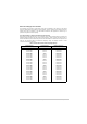
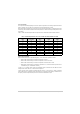
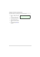
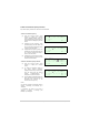
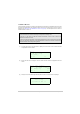
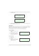
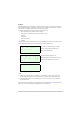
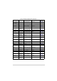
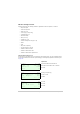
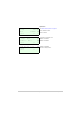
Table Of Contents
- Health and Safety
- Customer Support
- Abbreviations
- Overview
- Specification
- Operation
- Overview
- T6T VHF Amplifier
- Drive Assembly
- Setting Up and Operation
- Normal Operation
- Using the Scroll/Select Switch
- Screen Protocol
- Menu System
- Menu Lock Screen
- Control Screen
- Notes for Setting Up the Transmitter
- Changing the Transmitter’s Operating Frequency
- To Store and Recall Frequency Channels
- To Initiate a BIT Test
- Standby Mode
- Settings
- AM-Voice Settings Procedure
- AM-MSK Mode Settings Procedure
- Mode 2 Settings Screen
- Mode 3 Settings Screen
- Polarities Screen AM-Voice and AM-MSK
- Mode 2 and Mode 3 Polarity Settings
- AM-Voice and AM-MSK BIT Screen
- Mode 2 and Mode 3 BIT Screen
- Software Configuration Screens
- Band Edges
- BIT Status Warning Screens
- Installation
- Warnings and Cautions
- Introduction
- Installing the Transmitter

T6T 300 Watt VHF Transmitter Page 47 Operation
Settings
Operational settings for the transmitter are configured at the front panel, through the VFP, or through an
associated MARC system (or compatible control system). Some settings can also be made remotely via
a T6 controller. The Settings screen is entered from the Control screen.
The settings that can be selected at the front panel Settings screen are:
❑ Mode: either AM-Voice, AM-MSK, Mode 2 or Mode 3
❑ Mode settings - allows the selected mode parameters to be set
❑ Polarities
❑ Band edges
❑ Reference frequency
❑ Backlight.
Note that the mode selection, reference frequency and backlight are set from this screen. When mode
settings, polarities and band edges are selected the user is taken to other screens.
General and mode specific settings, showing default values, are referenced in Table 8 on the following
page. Click on any required parameter by page number for further references.
M o d e A M V o i c e
M o d e S e t t i n g s
P o l a r i t i e s
E x i t > >
B a n d E d g e s
R e f F r e q 5 0 . 0 %
B a c k l i g h t 0 3 0 s
E x i t < < > >
B a c k
E x i t
Select AM-Voice, AM-MSK, Mode 2 or Mode 3.
Select for the mode specific Settings menu.
Select for the Polarities menu.
Select for band edge settings screen.
Align the transmitter reference frequency (Note 1).
Adjust the LCD’s backlight time out (Note 2).
Notes:
(1) Setting the transmitter reference frequency is a maintenance operation. The current value
should not be reset unless the correct test equipment is connected. See the Maintenance topic.
(2) The LCD backlight can be set for permanently on, off, or timed to stay on for a period between
15 and 120 seconds.