
User's Manual Part 1
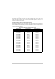
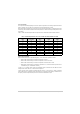
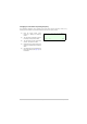
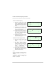
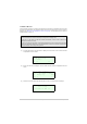
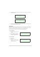
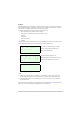
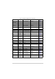
Table Of Contents
- Health and Safety
- Customer Support
- Abbreviations
- Overview
- Specification
- Operation
- Overview
- T6T VHF Amplifier
- Drive Assembly
- Setting Up and Operation
- Normal Operation
- Using the Scroll/Select Switch
- Screen Protocol
- Menu System
- Menu Lock Screen
- Control Screen
- Notes for Setting Up the Transmitter
- Changing the Transmitter’s Operating Frequency
- To Store and Recall Frequency Channels
- To Initiate a BIT Test
- Standby Mode
- Settings
- AM-Voice Settings Procedure
- AM-MSK Mode Settings Procedure
- Mode 2 Settings Screen
- Mode 3 Settings Screen
- Polarities Screen AM-Voice and AM-MSK
- Mode 2 and Mode 3 Polarity Settings
- AM-Voice and AM-MSK BIT Screen
- Mode 2 and Mode 3 BIT Screen
- Software Configuration Screens
- Band Edges
- BIT Status Warning Screens
- Installation
- Warnings and Cautions
- Introduction
- Installing the Transmitter

T6T 300 Watt VHF Transmitter Page 42 Operation
Line Level Setting
The input line level setting displayed on the front panel is equivalent to the average speech level with a
peak-to-average ratio of 13 dB. This corresponds to the level specified for the lines.
When testing the transmitter using a sine wave, the line input level should be set to 10 dB above the line
level setting. The VOGAD and mute thresholds are preset at 10 dB and 15 dB respectively below the line
level setting.
Table 7 shows the relationship between the input line level, VOGAD threshold and mute threshold.
Offset Carrier Operation
This transmitter can be set to operate using a 2, 3, 4 or 5-offset carrier system as follows:
❑ With 2-offset carrier working, the carriers are spaced at ±5 kHz
❑ With 3-offset carrier working, the carriers are spaced at zero and ±7.3 kHz
❑ With 4-offset carrier working, the carriers are spaced at ±2.5 kHz and ±7.5 kHz
❑ With 5-offset carrier working, the carriers are spaced at zero, ±4 kHz and ±8 kHz. [5-offset carrier
is available only on HS transmitter variants.]
If using a 2, 3 or 4-offset carrier system, the appropriate offset is selected from the AM-Voice mode
settings screen. After selection, no further action is required.
If using a 5-offset carrier system, the appropriate offset (-4 kHz, +4 kHz, -8 kHz or +8 kHz) is selected
from the AM-Voice mode settings screen. After selection, the procedure titled ‘Setting a 5-Offset Carrier
Frequency’ must be completed; this procedure is found in the Maintenance topic.
Table 7 Relationship Between Line Level, VOGAD Threshold and Mute Threshold
Line Level Setting
(dBm)
Average Speech
Level (dBm)
Sine Wave Level
(dBm)
VOGAD Threshold
(dBm)
Mute Threshold
(dBm)
+10 +10 +20 0 -5
+5 +5 +15 -5 -10
00+10-10-15
-5 -5 +5 -15 -20
-10 -10 0 -20 -25
-15 -15 -5 -25 -30
-20 -20 -10 -30 -35
-25 -25 -15 -35 -40
-30 -30 -20 -40 -45