
User's Manual Part 1

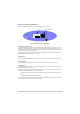
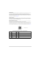
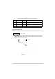
Table Of Contents
- Health and Safety
- Customer Support
- Abbreviations
- Overview
- Specification
- Operation
- Overview
- T6T VHF Amplifier
- Drive Assembly
- Setting Up and Operation
- Normal Operation
- Using the Scroll/Select Switch
- Screen Protocol
- Menu System
- Menu Lock Screen
- Control Screen
- Notes for Setting Up the Transmitter
- Changing the Transmitter’s Operating Frequency
- To Store and Recall Frequency Channels
- To Initiate a BIT Test
- Standby Mode
- Settings
- AM-Voice Settings Procedure
- AM-MSK Mode Settings Procedure
- Mode 2 Settings Screen
- Mode 3 Settings Screen
- Polarities Screen AM-Voice and AM-MSK
- Mode 2 and Mode 3 Polarity Settings
- AM-Voice and AM-MSK BIT Screen
- Mode 2 and Mode 3 BIT Screen
- Software Configuration Screens
- Band Edges
- BIT Status Warning Screens
- Installation
- Warnings and Cautions
- Introduction
- Installing the Transmitter

T6T 300 Watt VHF Transmitter Page 35 Operation
Standby Indicator
A red indicator that lights when the transmitter is in standby mode. When in standby mode, most of the
radio's circuits are inactive, the front panel LCD is blanked, and the transmitter cannot be keyed.
Standby mode is selected and deselected using the front panel Scroll/Select switch and LCD, by initiating
an instruction through a MARC system, through a T6 controller or through the VFP. For details of front
panel selection and deselection see page 46.
Reference Connector
An SMB jack socket that allows a frequency counter to monitor the transmitter's reference frequency.
This connector is used only for maintenance purposes. The instructions for checking and adjusting the
reference frequency are given in the Maintenance topic.
Microphone/Diagnostics Connector
A dual purpose connector that allows either a microphone, or a PC, to be connected to the transmitter.
The connector is a 7-pin self-locking DIN socket; the pin-out is shown in Table 4.
A microphone is fitted to this connector to enable the transmitter to be operated in AM local mode. The
connections are detailed in Table 4. A PC can also be connected to allow the VFP to be displayed. Using
the VFP is detailed in the Maintenance topic. The PC connections at the transmitter are shown in Table 5.
Table 4 Microphone/Diagnostics Connector - Audio Connections
Pin
Number
Signal
Input or
Output
Description
1 Microphone ground - 0 V.
3 Microphone PTT Input 0 V to PTT.
5 Sidetone Output 0 to 3 V pk-pk.
6 Microphone input Input 2 to 35 mV rms on Passive setting and 8 to 140 mV rms on
Active setting to remain in VOGAD range.
7 Ground - 0 V.
Viewed from front