
User's Manual Part 1
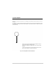

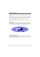
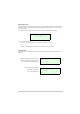
Table Of Contents
- Health and Safety
- Customer Support
- Abbreviations
- Overview
- Specification
- Operation
- Overview
- T6T VHF Amplifier
- Drive Assembly
- Setting Up and Operation
- Normal Operation
- Using the Scroll/Select Switch
- Screen Protocol
- Menu System
- Menu Lock Screen
- Control Screen
- Notes for Setting Up the Transmitter
- Changing the Transmitter’s Operating Frequency
- To Store and Recall Frequency Channels
- To Initiate a BIT Test
- Standby Mode
- Settings
- AM-Voice Settings Procedure
- AM-MSK Mode Settings Procedure
- Mode 2 Settings Screen
- Mode 3 Settings Screen
- Polarities Screen AM-Voice and AM-MSK
- Mode 2 and Mode 3 Polarity Settings
- AM-Voice and AM-MSK BIT Screen
- Mode 2 and Mode 3 BIT Screen
- Software Configuration Screens
- Band Edges
- BIT Status Warning Screens
- Installation
- Warnings and Cautions
- Introduction
- Installing the Transmitter

T6T 300 Watt VHF Transmitter Page 31 Operation
T6T VHF Amplifier
There are no operating controls fitted to the amplifier. All operational settings are made at the drive
assembly.
The amplifier has three front panel indicators as detailed in Fig 6 and a rear panel Supply switch. Should
an amplifier fail, shown by the Alarm indicator being lit, the transmitter continues to operate at reduced
power (200 watts).
Fig 6 T6T VHF Amplifier Front Panel Indicators
Ready. A green indicator that lights when the amplifier is ready for
use and no BIT faults have been detected.
Alarm. A red indicator that lights when a BIT fault has been
detected.
Transmit. An amber indicator that lights when the transmit circuit is
keyed and the amplifier is producing output power.