
User's Manual Part 1


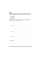

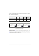

Table Of Contents
- Health and Safety
- Customer Support
- Abbreviations
- Overview
- Specification
- Operation
- Overview
- T6T VHF Amplifier
- Drive Assembly
- Setting Up and Operation
- Normal Operation
- Using the Scroll/Select Switch
- Screen Protocol
- Menu System
- Menu Lock Screen
- Control Screen
- Notes for Setting Up the Transmitter
- Changing the Transmitter’s Operating Frequency
- To Store and Recall Frequency Channels
- To Initiate a BIT Test
- Standby Mode
- Settings
- AM-Voice Settings Procedure
- AM-MSK Mode Settings Procedure
- Mode 2 Settings Screen
- Mode 3 Settings Screen
- Polarities Screen AM-Voice and AM-MSK
- Mode 2 and Mode 3 Polarity Settings
- AM-Voice and AM-MSK BIT Screen
- Mode 2 and Mode 3 BIT Screen
- Software Configuration Screens
- Band Edges
- BIT Status Warning Screens
- Installation
- Warnings and Cautions
- Introduction
- Installing the Transmitter

T6T 300 Watt VHF Transmitter Page 18 Overview
Models and Part Numbers
Table 1 identifies a T6T 300 watt VHF transmitter.
Fig 4 shows the identification labels attached to each component. Each label identifies the model, part
number, serial number and modification level.
Fig 4 Identification Label Examples
Mechanical Installation
The transmitter, as shown in Fig 1, fits into an industrial standard 19 inch (483 mm) equipment cabinet
and occupies, in total, 14U of cabinet space. Additionally, the combiner must be mounted at the back of
the equipment cabinet directly behind the amplifiers’ cooling fans. A bracket provided (shown fitted in
Fig 2) is used to mount the combiner on a cabinet upright.
Table 1 Model Identification
Description Part Number Frequency Range Channel
Spacing
(AM-Voice)
Special
Applications
T6T 300 watt standard frequency
coverage, high stability, VHF
transmitter
B63300HS 118 to 136.975 MHz 25 kHz or
8.33 kHz
Supports 5-offset
carrier operation
Model:
Part No:
S / No:
Mod Record:
T6T VHF Drive Assembly
24-06633001/3
2L0001
X 6 7 8 9 10 11 12 13
Park Air Systems Ltd England
PAE
Model:
Part No:
S / No:
Mod Record:
T6T VHF Amplifier
24-31633001/2
2L0001
X 6 7 8 9 10 11 12 13
Park Air Systems Ltd England
PAE
Model:
Part No:
S / No:
Mod Record:
T6T VHF Combiner
24-33633001/2
2L0001
1 2 3 4 5 6 7 8 9 10
Park Air Systems Ltd England
PAE
Drive Assembly Identification Label Amplifier Identification Label Combiner Identification Label