
User's Manual Part 1


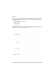
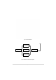
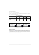

Table Of Contents
- Health and Safety
- Customer Support
- Abbreviations
- Overview
- Specification
- Operation
- Overview
- T6T VHF Amplifier
- Drive Assembly
- Setting Up and Operation
- Normal Operation
- Using the Scroll/Select Switch
- Screen Protocol
- Menu System
- Menu Lock Screen
- Control Screen
- Notes for Setting Up the Transmitter
- Changing the Transmitter’s Operating Frequency
- To Store and Recall Frequency Channels
- To Initiate a BIT Test
- Standby Mode
- Settings
- AM-Voice Settings Procedure
- AM-MSK Mode Settings Procedure
- Mode 2 Settings Screen
- Mode 3 Settings Screen
- Polarities Screen AM-Voice and AM-MSK
- Mode 2 and Mode 3 Polarity Settings
- AM-Voice and AM-MSK BIT Screen
- Mode 2 and Mode 3 BIT Screen
- Software Configuration Screens
- Band Edges
- BIT Status Warning Screens
- Installation
- Warnings and Cautions
- Introduction
- Installing the Transmitter

T6T 300 Watt VHF Transmitter Page 16 Overview
Purpose
The T6T 300 watt VHF transmitter is intended for use in fixed ground environments such as airports and
en-route centres. The transmitter operates in voice and ICAO defined data modes at frequencies
between 118 and 136.975 MHz. Dependent on the software loaded into the radio, the following operating
modes can be selected:
❑ AM-Voice. All transmitters have this mode
❑ AM-MSK (optional)
❑ Mode 2 (optional)
❑ Mode 3 (optional).
The transmitter, see Fig 1 and Fig 2, consists of a drive assembly, three 100 watt amplifiers and a
combiner. The transmitter is configured as shown in Fig 3. Should any one of the amplifiers fail, the
transmitter continues to operate at reduced (200 watt) power.
Fig 1 T6T 300 Watt VHF Transmitter
T6T VHF Amplifier
T6T VHF Amplifier
T6T VHF Amplifier
T6T VHF Drive Assembly