FS-52 INNER / OUTER THIGH ASSEMBLY MANUAL AM-FS52
A MESSAGE TO OUR CUSTOMERS Thank you for purchasing the Paramount FS-52 Inner / Outer Thigh machine. Because of the many unique features included in this product, this manual was created to provide you with information on how to properly assemble and maintain your equipment. Proper maintenance will ensure that your new equipment will last for years.
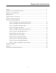
TABLE OF CONTENTS SAFETY...................................................................................................................... 4 GENERAL CARE AND MAINTENANCE........................................................................... 5 DIMENSIONS AND WEIGHT........................................................................................... 6 PREPARATION.............................................................................................................
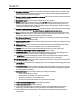
SAFETY 1. Review and understand all of the warning labels affixed to this machine and on the facility safety sign. Replace any warning label at first sign of wear. Labels and the Facility Safety Sign may be obtained from Paramount free of charge. 2. Be certain that the machine operation is understood before it is used. Refer to the instruction label provided with the machine. 3. Keep children away from this equipment. Supervise use by teenagers. 4. DO NOT high-pin or double-pin the weight stack.
GENERAL CARE AND MAINTENANCE 1. Cable Ends: Inspect end fittings daily for wear. Replace cables at the first sign of wear or on an annual basis. If the cable tension has been adjusted, be certain that the cable nut is tight. 2. Nuts, Bolts, and Fasteners: Check tightness weekly. If any hardware has become loose, retighten and/or use LoctiteTM brand Threadlocker 242. 3. Frames: Wipe all machines down with a damp cloth and dry completely each day.
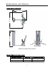
DIMENSIONS AND WEIGHT “IN USE” MACHINE DIMENSIONS 64.5” (164 cm) 67.0” (170 cm) 60.5” (154 cm) Maximum user weight: 300 lbs. (136 KG) MACHINE WEIGHT AND FLOOR LOADING WEIGHT STACK CONFIGURATION MACHINE WEIGHT APPROXIMATE FLOOR LOADING 170 lbs. 455 LBS [206 KG] 66 LBS/FT2 [322 KG/M2] 250 lbs.
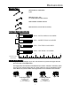
PREPARATION REQUIRED TOOLS: Ratchet Wrench and Sockets: 9/16” Wrenches: 9/16”, 3/4”. (or an adjustable crescent wrench). Rubber Mallet and Steel Hammer Allen wrenches: (included with the machine) Hardware Measurement Guide: BHCS - BUTTON HEAD CAP SCREW SHCS - SOCKET HEAD CAP SCREW FHCS - FLAT HEAD CAP SCREW HHCS - HEX HEAD CAP SCREW 1 2 3 4 5 MEASURE BOLT FROM HERE Weight Plate Cartons: Weight plates are packaged (4) per box. You should have (4) boxes of weights.
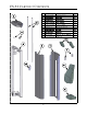
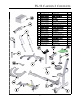
FS-52 CARTON 1 CONTENTS ITEM 1 2 6 PART NO. DESCRIPTION QTY.
FS-52 CARTON 2 CONTENTS ITEM 13 5 6 7 PART NO.
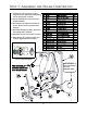
STEP 1: ASSEMBLE THE FRAME COMPONENTS 1. Position the main frame and upright frame. Route the cable before assembling the two components as shown. 2. Loosely assemble the main frame and upright hardware. 3. Pre-assemble the right arm and axle as shown. Tap the pins into position with a hammer. 4. Assemble the thigh pad plate. Tap the pin into position with a hammer. 5. Assemble the arm to the frame as shown. 6. After aligning all component edges and surfaces, tighten ALL the hardware.
STEP 1: ASSEMBLE THE FRAME COMPONENTS 12 12 NOTE: MAKE SURE THIGH PAD PLATE IS ORIENTED AS SHOWN BEFORE INSTALLING RETAINING PIN.
STEP 2: ASSEMBLE THE ADJUSTMENT PLATE 1. Assemble the cam to the axle and tighten the hardware. The cam can only be assemble to the axle in one orientation. 2. Pre-assemble the axle, the Pulley Arm and the adjustment plate. Make to sure orient the adjustment plate as shown and then install the roll pins using a hammer. ITEM PART NO.
STEP 3: ASSEMBLE THE LEFT ARM 1. Assemble the left arm to the axle. ITEM PART NO. DESCRIPTION QTY. 2. Assemble the arm retaining assembly and tighten the hardware. 1 FS52-ARM-000X LEFT ARM 1 2 FS52-MFR-300X THIGH PAD PLATES 1 3. Install the roll pin using a hammer. Make sure the arm is able to be in the position shown.
STEP 4: ASSEMBLE THE PADS 1. Assemble the pads and hardware as shown. 2. Tighten ALL the hardware. 3. Note: make sure the thigh pads can be assembled as shown. If they can not, the thigh pad plates have been installed incorrectly. Refer to Steps 1 and 3. ITEM PART NO. DESCRIPTION 1 C 451 SCREW, 3/8”-16 X 2-3/4” HHCS QTY.
STEP 5: ASSEMBLE THE CONNECTING PLATE 1. Assemble the connection arm and hardware as shown. The arms will have to be positioned so that the plate can be attached ITEM PART NO. DESCRIPTION QTY. 1 FS52-PLT-400X PLATE, ARM CONNECTION 1 2 C-766A LOCK NUT, 3/8”-16 2 3 C 754C WASHER, FLAT, 3/8” 2 2. Tighten the hardware.
STEP 6: INSTALL THE WEIGHT STACK 1. Place the guide rods in the upright. ITEM 2. Install the weight stack base, rubber bumpers, and washers. 3. Install the weight plates. 4. Install the cap plate and attach the cable with the selector pin as shown. 5. Install the Guide rod hubs and tighten the hardware. PART NO. DESCRIPTION QTY.
STEP 7A: INSTALL THE CABLES 1. Route the cable as shown, installing the associated pulleys and hardware as you go along. 2. After assembly, make sure the cable and pulleys can move freely. 3. Tighten ALL the hardware. ITEM PART NO. DESCRIPTION QTY. 1 B 900 PULLEY, 4-1/2” DIA.
STEP 7B: INSTALL THE CABLES 1. Route the cable as shown, installing the associated pulleys and hardware as you go along. 2. After assembly, make sure the cable and pulleys can move freely. ITEM PART NO. DESCRIPTION QTY. 1 B 900 PULLEY, 4-1/2” DIA. 1 2 C 448 SCREW, 3/8”-16 X 1-3/4” HHCS 1 3 C 802 SCREW, M4 X 20mm PAN HD. 1 4 C 754C FLAT WASHER, 3/8” 2 5 C 766A LOCKNUT, 3/8”-16 1 3. Tighten ALL the hardware.
STEP 8: INSTALL THE CAM COVER 1. Place the Cam Cover into place and loosely assemble the hardware. 2.Place the Small Cam Cover into place and loosely assemble the hardware. 3. Align the edges and then tighten ALL the hardware. ITEM PART NO. DESCRIPTION QTY.
STEP 9: INSTALL THE FRONT SHROUD 1. Place the front shroud into position. 2. Align the holes and assemble the hardware. 3. Tighten all the hardware. ITEM PART NO. DESCRIPTION 1 C 445 SCREW, 3/8”-16 X 1” HHCS 4 2 C 749 LOCK WASHER 4 3 C 754C FLAT WASHER 4 4 FS52-SHD-200X FRONT SHROUD 1 4 1, 2, 3 X4 20 QTY.
STEP 10: INSTALL THE REAR SHROUD 1. Set the lower screws of the shroud into the ITEM PART NO. 1 C 766A lower brackets on the upright frame. 2. Then align the holes for the brackets at the top of the shroud. 2 DESCRIPTION C 675D QTY. LOCKNUT, 3/8”-16 2 SCREW, 1/4”-20 X 1/2” BHCS 8 3 C 444 SCREW, 3/8”-16 X 3/4” HHCS 2 4 FS-SHD-250X REAR SHROUD 1 3. Assemble all the shroud hardware and tighten. 5 C 754C FLAT WASHER, 3/8” 4 6 FS-CAP-000X TOP CAP, UPRIGHT 1 4.
STEP 11: APPLY THE WEIGHT STACK LABEL 1. Select the appropriate weight stack label(s) according to your order. You can install pound labels, kilogram labels, or both. 2. If you ordered a 170 lb. weight stack, use labels: LBL-WSE-01170 (for pounds) LBL-WSM-01170 (for kilograms). 3. If you ordered a 250 lb. weight stack, use labels: LBL-WSE-01250 (for pounds) LBL-WSM-01250 (for kilograms). 4. Remove the backing from the label to expose the adhesive.
MACHINE LABELS The following are the Warning labels required for this FS machine. If any of these labels are missing or become damaged, Paramount will replace them free of charge. Note: these labels are not to scale. ! WARNING ! MAX MAXIMUM Height Under Nut to Bolt Head. MAKE SURE locking nut is tight. WARNING SERIOUS INJURY CAN OCCUR ON THIS EQUIPMENT IF THE CABLES AND THEIR ATTACHMENT COMPONENTS ARE NOT INSPECTED OFTEN. REPLACE AT FIRST SIGNS OF WEAR.
SERVICE HOW TO OBTAIN SERVICE For warranty service, contact an Authorized Paramount Dealer or a Paramount Customer Service representative at 1-800-721-2121 or 1-213-721-2121. Or by E-mail at nasales@paramountfitness.com. Before you call, please have the following information ready.
NOTES 25
PARAMOUNT LIMITED WARRANTY Paramount warrants to the original purchaser from a Paramount authorized dealer that Paramount equipment or equipment from a Paramount authorized manufacturing contractor will be free from defects in material and workmanship under normal use and service for the following periods and in the following respects: LIFETIME WARRANTY - Welds, Weight Plates and Guide Rods FIVE YEAR WARRANTY - Bronze Bushings, Sealed Rotating Bearings and Pulley Wheels ONE YEAR WARRANTY - Cables, Linear Be
Paramount Fitness Corporation 6450 E. Bandini Blvd. Los Angeles, CA 90040-3185 Phone: 1-323-721-2121 Fax: 323-724-2000 1-800-721-2121 www.paramountfitness.com AM-FS52-071207.