Comba Telecom Ltd. CWS-4240-71 HIGH POWER REMOTE RADIO HEAD PRODUCTION USER GUID The information contained herein is confidential and the property of Comba and is supplied without liability for errors or omissions. No part may be reproduced, disclosed or used except as authorised by contract or other written permission. The copyright and the foregoing restriction on reproduction and use extend to all me dia in which the information may be embodied.
Table of Contents 1. OVERVIEW.................................................................................................................................................... 1 1.1. COMPLIANCE ............................................................................................................................................ 1 1.2. APPEARANCE ............................................................................................................................................ 2 1.3.
Document History Page No.
List of Abbreviations Abbreviation 3GPP AC ANT BBU BTS CDMA CINR CLI CPICH CPRI CU DU DC DL FFT GUI GSM IFFT IP Rating IP LAN LED LMT LTE MIMO NMS NR PSU PHY RAN RF RSRP RSSI Rx SFP Tx UL UMTS VLAN Version: 1-0-1 (102019) Meaning 3rd Generation Partnership Project Alternating Current Antenna Baseband Unit Base Transceiver Station Code Division Multiple Access Carrier to noise ratio Command-Line Interface Common Pilot Channel Common Public Radio Interface Central Unit Distributed Unit Direct Current Down L
BLANK PAGE Version: 1-0-1 (102019) Page v
ENB35A77R Product Description 1. OVERVIEW High Power Remote Radio Head (RRH) is a part of Comba’s 4G/5G OPEN RAN solution. The CWS-4240-71 RRH is an outdoor remote radio head for macro BTS site. It built on the state-of-the-art Comba high power and efficient linear power amplifiers technology, innovative RF filter and industrial design. Featuring with a compact size, light-weight and low power consumption specification.
ENB35A77R Product Description 1.2. APPEARANCE The following figures shows the appearance of the CWS-4240-71 RRH. Figure 1.1.1 – 2T2R RRH 1.3. NETWORK ARCHITECTURE Following is the typical network architecture of Open RAN system, RRH is connected with the BBU or CU/DU by eCPRI fronthaul interface, the connection is optical fiber cable. The RF output of the RRH is connected to BTS antenna by RF cables. The BBU and RRH are powered by PSU in the equipment room or outdoor PSU. Figure 1.2.
ENB35A77R Product Description 1.4. PHYSICAL PORTS AND INDICATION DC-48V DEBUG OP2 OP1 Front Side Ports OP1 ACT PWR RUN/ALM OP2 VSWR LED Panel AISG/ MON GPS ANT1 ANT2 2T2R RRH bottom view Version: 1-0-0 (102019) Comba Confidential Copyright © Comba Telecom Ltd.
ENB35A77R Product Description Port Connecter Description OP 1 OP 2 DC -48V OMT SFP+ SFP+ 2-pin socket Mini-USB 10GE, eCPRI Fronthaul interface to BBU 10GE, eCPRI Fronthaul interface, cascade to RRH -48V DC power input Ethernet interface for LMT Table 1.3.1 Ports at front side Port ANT1 ANT2 GPS AISG/MON Connecter Description 4.3-10 (Female) 4.3-10 (Female) N (Female) DB-15 Antenna TRx Port 1 (2T2R, 4T4R) Antenna TRx Port 2 (2T2R, 4T4R) GPS Receiver antenna AIGS 2.0 interface Table 1.3.
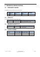
2. TECHNICAL SPECIFICATION 2.1. FREQUENCY BANDS The ENB25A77R support following FDD frequency bands; LTE Band Frequency Band TX Frequency (MHz) RX Frequency (MHz) IBW (MHz) B71 600 617 – 652 663 – 698 35 Table 2.1.1 RRH frequency bands 2.2. CAPACITY The Capacity of CWS-4240-71 are list in below tables; Mode Frequency Band Capacity LTE 600 4 carriers (5/10/15/20MHz), 2T2R Table 2.2.1 Single-mode capacity 2.3.
2.5. ELECTRICAL SPECIFICATION 2.5.1. INPUT POWER VOLTAGE Normal Voltage Operation Voltage Range -48V DC -36V to -57V DC Table 2.5.1.1 Input power voltage 2.5.2. POWER CONSUMPTION Mode No. of Carriers LTE Output Power per carrier (W) 4 Typical Power Consumption (W) Maximum Power Consumption (W) 200 297 43 Table 2.5.2.1 Power consumption 2.6. MECHANICAL AND ENVIRONMENTAL SPEFICATION 2.6.1. EQUIPMENT SIZE AND WEIGHT Dimension (H x W x H) Weight 400mm x 300mm x 126mm 14.
3. INSTALLATION INSTRUCTIONS 3.1. PACKING LIST NO 1 Description Model high power remote CWS-4240- radio head 71 Quantity Remarks 1 Pcs ACCESSORIES INCLUDED NO 3.2. Description Item code Quantity Remarks Diameter Length 1 GND Cable 6#AWG,2m 1 Pcs / / 2 U-bolt M10×85×110 2 Pcs 10mm 275mm 3 Expansion bolt M10×110 4 Pcs 12.
1(RRH-3522-5831) to the RRH enclosure, as shown in Figure 1. Enclosure Mounting Bracket 1 4-M6x16 Screw Figure 1 RRH Hanger Installation Diagram Step 2: use 2 U-Bolt to install the mounting bracket 2(RRH-3522-5832) to the pole(the diameter of the pole should less than 75 mm), as shown in Figure 2.
M5x18 Screw Figure 3 RRH Pole-mount Complete Diagram b) Wall-mount Installaion Instructions: Step 1: take out the RRH from the package, use 4 M6 x 16 screws to fix the mounting bracket 1(RRH-3522-5831) to the RRH enclosure, as shown in Figure 4. Enclosure Mounting Bracket 1 4-M6x16 Screw Figure 4 RRH Hanger Installation Diagram Step 2: take out the mounting bracket 2(RRH-3522-5832), use percussion drill to drill 4 pole of Φ14 with 65-75 mm depth, as shown in Figure 5.
5 85 Figure 5 Wall-mounting Drilling Dimension Diagram Step 3: use hammer push 4 M10 expansion bolt into the hole of the wall, fix the mounting bracket 2(RRH-3522-5832) to the wall according the Figure 6. Wall 4-M10x110 Expansion Bolt 4-Ø14 Hole 85 Mounting Bracket 2 4-M10 Flat Washer 155 4-M10 Spring Washer 4-M10 Nut Figure 6 Mounting Bracket 2 Installation Diagram Version: 1-0-0 (102019) Comba Confidential Copyright © Comba Telecom Ltd.
Step 4: put the RRH prepared previous in step 1 insert to the mounting bracket 2, and lock the device with M5x18 screw, as shown in Figure 7. And Figure 8 illustrated the installation complete diagram. M5x18 Screw Figure 7 Wall-mounting Installation Diagram Figure 8 Wall-mounting Installation Complete Diagram 3.3.2. CABLE MAKING INSTRUCTIONS Version: 1-0-0 (102019) Comba Confidential Copyright © Comba Telecom Ltd.
Cable making specification is shown in Figure 9. 10 tripping length 30 OV -48V RPS0213089, 2PIN Power Plug 2 2×4.0 mm wire φ10.3±0.3 RVV2×4.0 mm , 2 Core(Blue Black) Power Cord Figure 9 Cable Making Specification Note: The maximum diameter of the DC power cord is 10.3mm. 3.3.3. GROUNDING The Grounding cable is provided with the screw which will be installed at the chassis as shown in Figure 10. The Grounding cable is yellow-green two-tone wire, type is 6 AWG.
3.3.4. BOTTOM PORTS Figure 11 Bottom Port Diagram Remark: for reference only, these parameters maybe change for the RRH is still in develop. Name Type Num. Des GPS N-type 1 GPS connector AISG/MON 15-pin circular 1 RET connector ANT1 4.3-10 1 Antenna TX1 connector ANT2 4.3-10 1 Antenna TX2 connector --End-- Version: 1-0-0 (102019) Comba Confidential Copyright © Comba Telecom Ltd.