
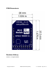
Data Sheet
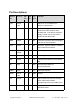

Pin Descriptions
Module
Pin
Direction
SIP
Pin
DIP
Pin
ESP
8266
Function
VIN
Power
input
1
1
(SIP) 3.3 V or 5 V power input
(DIP) 3.3 V power input
/PGM
Input
2
20
IO0
If held low during power up, ESP8266
boots into a mode ready for serial
firmware load. Can also be pulled low
rapidly, 4 times in a row to put Wi-Fi
module into AP+STA mode.
DBG
Output
3
9
IO2
Transmits information about exchanges
with the host microcontroller.
ASC
Output
4
15
IO5
Associate - high/low patterns indicating
Wi-Fi mode and connection
/CTS
Input /
Output
5
12
IO13
User configurable pin
/RTS
Output
6
16
IO15
User configurable pin
DO
Output
7
2
TXD
Transmits serial data to microcontroller
host
DI
Input
8
3
RXD
Receives serial data from
microcontroller host
/RES
Input
9
5
EN
Active-low reset line
GND
Power
input
10
10
GND
Ground
PS
Output
7
IO4
May be used in the future to remotely
switch a WX carrier board’s
programming source from USB to Wi-Fi
DTR
Output
18
IO12
Toggle’s microcontroller reset line in
WX carrier board
Copyright © Parallax Inc.
ESP8266 Wi-Fi Module (#32420)
v1.0 05/12/2016 Page 11 of 12