
Data Sheet

The pulse width is proportional to the distance, and does not significantly change with the
ambient temperature, pressure, or humidity.
To convert the pulse width from time, in µs, to mm, use the following equation:
Distance (mm) = Pulse Width (ms) × 171.5
To convert the pulse width from time, in µs, to inches, use the following equation:
Distance (inches) = Pulse Width (ms) × 6.752
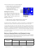
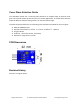
Serial Data Mode
Serial data mode works at 9600 baud with a bidirectional TTL interface on a single I/O pin (SIG),
and can communicate with 3.3 V or 5 V TTL or CMOS microcontrollers. The SIG pin will idle high
in this mode, at the VIN voltage.
To switch from the default PWM mode to serial mode, drive the SIG pin low, then send three
high 100 µs pulses with 5 µs, or longer, low gaps between. This can be done by transmitting a
capital ‘I’ character.
Tip: For use with microcontrollers that do not support bidirectional serial, the LaserPING
module can be configured to wake-up in serial mode. In this case, only a single serial-rx input
is required at your microcontroller! Refer to the section “Enabling Serial on Start-up” below.
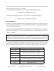
In Serial mode, LaserPING will constantly send new measurement data in ASCII format. The
value will be in millimeters, and followed by carriage return character (decimal 13). A new value
will be transmitted each time the sensor receives a valid reading, typically once every 45 ms.
Serial Value
Condition
50 to 2000
Highest accuracy measurement in millimeters
1 to 49
Reduced accuracy measurement in millimeters
2001 to 2046
2047
Reflection detected beyond 2046 millimeters
0 or 2222
Invalid measurement
(No reflection; target too close, too far, or too dark)
9998
Internal sensor error
9999
Internal sensor timeout
Copyright © Parallax Inc.
LaserPING Rangefinder Module (#28041)
v1.0 1/29/2018 Page 4 of 8