
Data Sheet

Copyright © Parallax Inc. Parallax Feedback 360° High-Speed Servo (#900-00360) v1.2 9/12/2017 Page 2 of 7
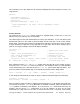
Quick-Start Circuit
Pin Descriptions
Pin
Name
Description
Min
Typical
Max
Units
Yellow
Feedback
Servo output, PWM, 910 Hz, 2.7–97.1% duty cycle
3.3
V
White
Control
Servo input, PWM, 50 Hz, 1280–1720 µs
3.3
3.3
5.0
V
Red
Vservo
Servo power supply
5*
6
8.4
V
Black
Vss
Ground, common ground with microcontroller
0
v
*5 VDC is absolute minimum required for no-load angular position control. 5.8 to 8 VDC is recommended
for continuous rotation speed control.
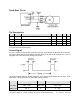
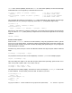
Control Signal
The servo requires an input control signal sent from your microcontroller via the white wire connection.
This signal, labeled tControl in the diagram and table below, is the time in microseconds of a 3.3 to 5 V
high pulse. The control signal must be sent every 20 ms.
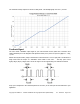
The duration (pulse width) of tControl determines servo rotation speed and direction as shown in the
table below. The top speed will vary with supply voltage and load.
Clockwise (faster to slower) Stop Counterclockwise (slower to faster)
tControl,
+/- 10 µs
1280….1480 1480...1520 1520….1720
RPM, +/-
15
140...0 0 0…-140