
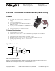
Continuous rotation servo v2.0

Copyright © Parallax Inc. Parallax Continuous Rotation Servo (#900-00008) v2.0 7/9/2009 Page 2 of 6
Device Information
The Parallax continuous rotation servo relies on pulse width modulation to control the speed and direction
of the servo shaft. Before utilizing the servo in a project, it is important to calibrate the center position of
the servo in order to define the point where the servo is at rest (see Calibration – “Center” the Servo
below).
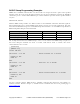
Specifications
Pin Name Description Minimum Typical Maximum Units
1 (White) Signal Input; TTL or CMOS 3.3 5.0 Vservo + 0.2 V
2 (Red) Vservo Power Supply 4.0 5.0 6.0* V
3 (Black) Vss Ground 0 V
*See Board of Education Servo Header Connection Diagram, page 2.
Power Precautions
y
Do not use this servo with an unregulated wall-mount supply. Such power supplies may deliver
variable voltage far above the stated voltage.
y Do not power this servo through the BASIC Stamp Module's Vin pin, this can deliver voltages
above the stated voltage. See the Board of Education Connection Diagram below for jumper
settings.
y Servo current draw can spike while under peak load; be sure your application's regulator is
prepared to supply adequate current for all servos used in combination.
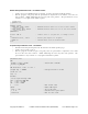
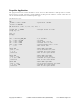
Board of Education Servo Header Connection Diagram
When connecting the servo to the Board of Education Rev C or higher’s servo header, be sure the jumper
is set to Vdd as shown in the figure below. Failure to place the jumper at this setting can cause damage
your servo!
Black
Red
X4 X5
15 14 13 12
Vdd
Vin
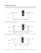
Calibration – "Center" the Servo
The servo has a potentiometer access port, allowing the user to adjust the servo to hold completely still
when receiving a 1.5 ms pulse width. This is the value in the "center" of the range of control pulses the
servo will accept.
To center the servo, program your host device to deliver a 1.5 ms pulse, continually refreshed every 20
ms. Sample calibration code is given below for all BASIC Stamp models, Spin for the Propeller, and SX/B
for the SX chip. All are available for download from the 900-00008 product page at www.parallax.com
.
Connect the servo to your microcontroller's I/O pin. The example programs below specify an I/O pin.
Program