
User Guide
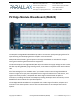
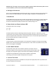
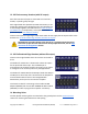


Programming Header Pin Assignments
The P2 Edge Module Breadboard uses the following markings for the programming header pins
located near the top left of the breadboard : ▽ △ RESn GND
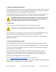
The arrows point inward (toward) the pad for RX and outward (away from) the pad for TX.
When using a serial programming device, such as Prop Plug, ensure that the Prop Plug TX pin
connects to the P2 Edge RX pin, and that that Prop Plug RX pin connects to the P2 Edge TX pin.
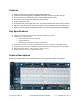
Recommend and Absolute Maximum Ratings
Programming Software
Propeller Tool is our recommended tool for programming the P2 Edge Module in SPIN and
PASM languages. Other programming languages are possible using third party tools, such as C,
BASIC, Forth.
You can find links to the latest tools at the Propeller 2 Software section of www.parallax.com.
Copyright © Parallax Inc. P2 Edge Module Breadboard (#64020) v1.1 11/30/2020 Page 9 of 11
Other
Pins
Description
RESn
Internally pulled up to 3.3V with 10K resistor.
Propeller chip will reset when RESn driven low; all cogs disabled and I/O pins floating.
Propeller restarts 3 ms after RESn transitions from low to high.
5V
Power input pins for the Edge Module. Connect both 5V edge connector pads to a good
quality 5VDC supply. The supply voltage MUST NOT exceed 5.5V!
Recommended minimum supply current 100mA, up to 3A depending on customer code and
circuit. Factors contributing to current requirements include operating frequency, number of
operating cogs, smart pin instruction types and external I/O circuitry.
GND
Provides common signal and supply voltage ground. Connection of all edge connector GND
pads to a solid ground plane on an external layer recommended.
NC
Not Connected. Reserved for future use.
Recommended “Do Not Connect” in customer designs.
Symbol
Quantity
Recommended
Maximum
Units
5 VDC
DC Barrel Jack Supply Voltage †
5
5.5
V
P0 - P63
Any I/O Pin
3.3
3.6
V
RESn
Reset input, active low
3.3
3.6
V