
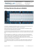
User Guide
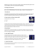


12. I/O Pin Accessory Headers (with 5V output)
Each of the 64 smart I/O pins is connected to an accessory
header, in specific groups of eight.
Each edge header also provides two GND connections, a Vxx
output pin supplying the voltage from the corresponding 3.3
V LDO voltage regulator, described above in VIO 3.3V Power
and GND Access, and optionally a 5 V output connection
(controlled by the ACC ON/OFF Header).
There are two special usage edge header banks which do not supply the 5V output. Refer to the
details here: I/O Pin Breakout Edge Headers (without 5V output)
CAUTION! Do not apply voltage to the Vxx Pin; it is a voltage output! Be aware
that some I/O pins are also connected to other peripheral circuits; see the Edge
Connector Pin Assignments section.
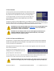
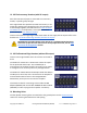
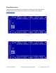
13. I/O Pin Breakout Edge Headers (without 5V output)
There are two edge headers which do not have 5V routed to
them.
The header for P24 to P31 is shown with a white silk square
for the pin beside the Vxx pin. This unlabelled pin is
unconnected, but could be used for connecting a user signal
or voltage to a user accessory board or prototype board.
The header for P56 to P63 has the RES pin beside the V56 pin.
The RES pin is active low, and is connected to the Propeller 2
microcontroller RESn circuit on the P2 Edge Module.
Momentarily set this pin low to reset the Propeller.
This header is ideal for connecting to the Parallax P2 WX
Adapter (#64007) with the Parallax ESP8266 SIP WiFi module
(#32420S) in order to program the Propeller 2 wirelessly.
14. Mounting Holes
The four plated mounting holes are attached to the ground plane. See the PCB Dimensions
section for mounting hole dimensions and spacing.
Copyright © Parallax Inc. P2 Edge Module Breadboard (#64020) v1.1 11/30/2020 Page 6 of 11