
User Guide


300 mA total). If a larger current common supply is required, add an alternative power source
to the breadboard, such as the Parallax Power Pal (#32133).
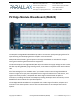
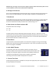
6. P2 Edge I/O Pin Access
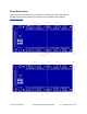
Access to the P2 Edge Module smart I/O pins P0...P63. Use jumper wires to connect these I/O
pins to circuits on the breadboard. In the above image, the I/O pins are labelled 48 to 55.
7. Breadboard
The breadboard area has dual 30 x 5-socket rows arranged in 2 columns, for a total of 60 rows.
The columns are separated by a valley in the middle. Any two wires plugged into the same
5-socket row become electrically connected. The socket spacing is 0.1”
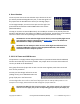
8. Power Switch and Power Indicator LED
The power switch has 2 settings:
• 0 — off
• 1 — on
The white power indicator LED will light when the power switch is on. Not that in certain
circumstances, if the power supply is disconnected while the power switch is still on, you may
notice the power LED remains lit for a period of time. This is normal and expected behaviour
due to the bulk capacitors included in the circuit.
9. Reset Button
Use this button to restart the Propeller 2 microcontroller’s program running on the P2 Edge
Module. Press and hold to keep the microcontroller in reset. Press and release to reset, load
and run the program in EEPROM.
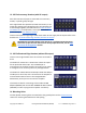
10. ACC ON/OFF Header
The 3-position 2mm pitch shunt headers allow the 5V output at the P2
accessory headers to be connected or disconnected from the DC Barrel Jack
5V supply. The 5V power supply is connected to the middle pin labeled 5V,
so position the provided shunt jumper either upward or downward,
connecting 5V to either the ON or OFF position as required.
11. Ground Test Posts
The four ground test posts are suitable for test clips and scope probes; two are positioned at
the top and bottom of the board.
Copyright © Parallax Inc. P2 Edge Module Breadboard (#64020) v1.1 11/30/2020 Page 5 of 11