
User Guide
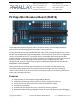
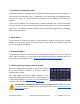
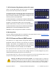


Edge Connector Pin Assignments
Smart I/O pins P0–P55 are fully free; P56–P63 are routed to peripheral circuits and/or have
special P2 boot sequence related functions. See the Propeller 2 documentation at
www.parallax.com for full details of P2 smart I/O pin capability.
Copyright © Parallax Inc. P2 Edge Mini Breakout Board (#64019) v1.1 11/30/2020 Page 8 of 10
I/O Pin
Description
P0-P7
Smart I/O pins, 3.3 V logic level, source or sink 30 mA per I/O pin. On-board LDO regulator
supplies 300 mA total, shared by this I/O pin group and edge connector pin V00.
P8-P15
Smart I/O pins, 3.3 V logic level, source or sink 30 mA per I/O pin. On-board LDO regulator
supplies 300 mA total, shared by this I/O pin group and edge connector pin V08.
P16-P23
Smart I/O pins, 3.3 V logic level, source or sink 30 mA per I/O pin. On-board LDO regulator
supplies 300 mA total, shared by this I/O pin group and edge connector pin V16.
P24-P31
Smart I/O pins, 3.3 V logic level, source or sink 30 mA per I/O pin. On-board LDO regulator
supplies 300 mA total, shared by this I/O pin group and edge connector pin V24.
P32-P39
Smart I/O pins, 3.3 V logic level, source or sink 30 mA per I/O pin. On-board LDO regulator
supplies 300 mA total, shared by this I/O pin group and edge connector pin V32.
P40-P47
Smart I/O pins, 3.3 V logic level, source or sink 30 mA per I/O pin. On-board LDO regulator
supplies 300 mA total, shared by this I/O pin group and edge connector pin V40.
P48-P55
Smart I/O pins, 3.3 V logic level, source or sink 30 mA per I/O pin. On-board LDO regulator
supplies 300mA total, shared by this I/O pin group and edge connector pin V48.
P56-P63
Smart I/O pins, 3.3 V logic level, source or sink 30 mA per I/O pin. On-board LDO regulator
supplies 300 mA total, shared by this I/O pin group and edge connector pin V56.
Alternative functions for P56-P63
P56
Buffered LED
P57
Buffered LED
P58
Flash SPI DO (MISO)
P59
Flash SPI DI (MOSI)
P60
Flash SPI CLK
P61
Flash SPI CS
P62
Prop-Plug RXD (P2 TXD)
P63
Prop-Plug TXD (P2 RXD)
Other
Description
RESn
Internally pulled up to 3.3V with 10K resistor. P2 will reset when RESn driven low.
5V
Power input pins for the Edge Module. Connect both 5V edge connector pads to a good
quality 5VDC supply. The supply voltage MUST NOT exceed 5.5V!
Recommended minimum supply current 100mA, up to 3A for heavy load and multi-cog use.
GND
Provides common signal and supply voltage ground. Connection of all four edge connector
GND pads to a solid ground plane on an external layer recommended.
NC
Not Connected, reserved for future use. Recommended “Do Not Connect” in designs.