
User Guide
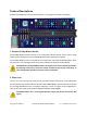


3. Prop Plug Programming Header
The P2 Edge Module is programmed by the Parallax Prop Plug programming tool (#32201). To
accommodate the Prop Plug, there is a dedicated 4-pin programming and debugging header.
The pins are marked ▽ △ RES VSS, and correspond to the pin labelling on the Prop Plug
adapter.
Connect the Prop Plug to your computer with a suitable USB cable. Then, insert the Prop Plug
onto the header pins with the Prop Plug components facing upward. The upward orientation
allows you to see the RX and TX activity LEDs on the Prop Plug while programming or debugging
data is being transmitted.
4. Reset Button
Use this button to restart the Propeller 2 microcontroller’s program running on the P2 Edge
Module. Press and hold to keep the microcontroller in reset. Press and release to reset, load
and run the program in EEPROM.
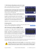
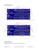
5. Protoboard Matrix
The protoboard areas are unconnected 4 x 5 hole matrices arranged in 2 areas, for a total of 40
holes. The hole spacing is 0.1”. Use these to add components and access additional Smart I/O
pins directly from the Edge connector. Refer to the Edge Socket Pinout for details.
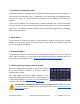
6. I/O Pin Accessory Headers (with 5V output)
With the P2 Edge Module plugged in, Each of the Propeller
2's 64 smart I/O pins connect to an accessory header, in
specific groups of eight.
Each edge header provides two GND connections, a Vxx
output pin supplying the voltage from the corresponding 3.3
V LDO voltage regulator (described here), and optionally a 5
V output, that is connected directly to the Power Jack.
DO NOT APPLY VOLTAGE TO THE Vxx Pin; it is a voltage output! Be aware that some
I/O pins are also connected to other peripheral circuits; see the Edge Connector Pin
Assignments section.
Copyright © Parallax Inc. P2 Edge Mini Breakout Board (#64019) v1.1 11/30/2020 Page 5 of 10