
QTI line sensor rev 1.0
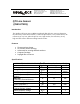
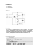
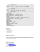
Table Of Contents

' -----[ Constants ]--------------------------------------
----------------------
ClrEOL CON 11 ' clear to end of line (DEBUG)
' -----[ Variables ]--------------------------------------
----------------------
Sense VAR Word ' sensor raw reading
' -----[ Main Code ]--------------------------------------
----------------------
Read_Sensor:
HIGH LineSnsrPwr ' activate sensor
HIGH LineSnsrIn ' discharge QTI cap
PAUSE 1
RCTIME LineSnsrIn, 1, Sense ' read sensor value
LOW LineSnsrPwr ' deactivate sensor
Display:
DEBUG Home
DEBUG "Sensor ", CR
DEBUG "-----", CR
DEBUG DEC Sense, ClrEOL
PAUSE 100
GOTO Read_Sensor
Dimensions
PCB Length: 1”
Overall Length: 1 ¼”
PCB Width: 3/8”
Thickness: 5/16”
Trouble Shooting Tips
Make sure that the QTI sensor is properly installed by matching up the pins. The “B”
connects to Vss. The “R” connects to pin 9 of the BASIC Stamp and the “W” connects
to pin 10 of the BASIC Stamp.
BASIC Stamp support:
Web:
www.parallax.com
E-mail: support@parallax.com
Fax: (916) 624-8003
Phone: (916) 624-8333