
QTI line sensor rev 1.0
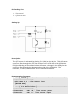
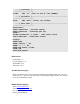
Table Of Contents

Kit Packing List
1. This manual
2. QTI sensor unit
Setting Up
Description
The QTI sensor is activated by placing 5 V (Vdd) on the W pin. This will cause
current to flow through the 470 ohm resistor to the LED side of the QRD1114.
IR light reflecting of the surface below will cause a change in the ability for the
current to flow through the phototransistor side of the QRD1114. The
transistor, in effect, behaves like an IR controlled resistance.
Demonstration Programs
' -----[ Title ]------------------------------------------
----------------------
' Mini-Sumo 3.1 : Line Sensor Test
' {$STAMP BS2}
' -----[ I/O Definitions ]--------------------------------
----------------------
LineSnsrPwr CON 10 ' line sensor power
LineSnsrIn CON 9 ' line sensor input