
Data Sheet
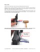
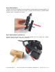


Step 6: Bearing Block and Axle Assembly
Using (3) 50 mm hex-head socket screws, and (3) 1” x 0.5” standoffs, attach the motor/drive axle
assembly to each of the motor bearing blocks as shown.
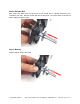
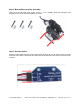
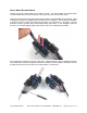
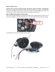
Step 7: Encoder Cables
Plug the encoder cables into each of the encoder boards as shown. Be sure to match the wire color with
the B-R-W color-coding on the boards. The white wires will be adjacent to each other in the center of the
connector.
Copyright © Parallax Inc. Motor Mount and Wheel Kit -AL(#228962) –MP(#28963) v1.1 1/21/2015 Page 6 of 13