
Data Sheet


36-position Quadrature Encoder Operation
The 36-position Quadrature Encoders provide a convenient means to reliably track the position and speed
of each wheel at all times. With the (included) Encoder disks, each Encoder assembly has a basic
resolution of 36 positions per rotation. However, because there are two sensors in each assembly, this
results in a potential resolution of 144 positions per full tire rotation. This translates to a linear resolution
of approximately 0.13 inches of travel per drive assembly, using the stock six-inch tires. Actual resolution
will be limited by the amount of backlash in each of the gear motor assemblies, which is approximately
+/- 0.175 lineal inches.
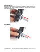
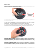
The 36 Position Quadrature Encoder Kit employs a dual-slotted sensor mounted on a printed circuit board
(PCB). This module contains a single infrared light source on one side of its slot, and two separate
sensors embedded into the opposite side of the slot.
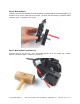
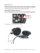
When the encoder disk rotates and swings through the slot, each individual fin on the disk blocks first
one sensor, and then the other, from the light source. The first blocked sensor transitions from low to
high, and then, as the encoder disk continues to rotate, the second sensor is blocked and it too
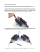
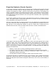
transitions from low to high. These two signals overlap each other, as shown in the diagram below.
In the diagram, notice that after sensor 1 goes high (A), sensor 2 then goes high (B) as the encoder
continues to rotate. Then, as the encoder continues to spin, sensor 1 goes low (C), and then sensor 2
follows (D). Because sensor 1 went high before sensor 2 (A-B), this indicates that the encoder disk is
rotating in one direction (in the case of a robot, either forward or reverse). If sensor 2 went high before
sensor 1, then the disk is rotating in the opposite direction. By interpreting these two signals, the
following can be determined:
• Whether or not the device is moving (by detecting transitions on either sensor).
• The direction in which the device is moving (by detecting which sensor transition occurs first).
• The speed at which the device is moving—by measuring the widths of each pulse, or by
measuring the frequency of the pulses.
• The total distance traveled (by counting the number of pulses from either sensor).
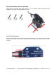
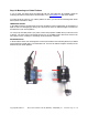
The Quadrature Encoders are compatible with most any microcontroller. Keep in mind that the Encoders
provide pure, real-time data; there is no processing delay on the Encoder board itself. The Encoder
delivers two high-speed output channels (through the white wires) to the circuit (or microcontroller) of
your choice.
Copyright © Parallax Inc. Motor Mount and Wheel Kit -AL(#228962) –MP(#28963) v1.1 1/21/2015 Page 12 of 13