
Robotics with the Boe-Bot text v2.2


Chapter 2: Your Boe-Bot’s Servo Motors · Page 65
P15
P14
P11
P10
P9
P8
P13
P12
X3
Vdd VssVin
(916) 624-8333
www.parallaxinc.com
www.stampsinclass.com
Rev B
P15
P14
P11
P10
P9
P8
P13
P12
X3
Vdd
VssVin
(916) 624-8333
www.parallaxinc.com
www.stampsinclass.com
Rev B
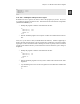
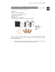
Figure 2-18
Servo
Connection
Wiring
Diagram for
the BASIC
Stamp
HomeWork
Board
Left (build
the servo
ports).
Right
(connect
the servos).
Port connections Servo connections by wire color
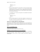
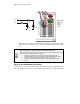
Your setup will then resemble Figure 2-19.
Figure 2-19
Dual Supplies
and Servos
Connected
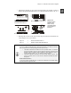
√ Rebuild the LED circuit as shown in Figure 2-20.
Å White
Å Red
Å Black
Å Red
Å Whi
te
Å P13
Å Vbp
Å Vss
Å Vbp
Å P12
Solid Black
Wire
Black wire with
white stripe