
Robotics with the Boe-Bot text v2.2


Page 314 · Robotics with the Boe-Bot
P14
Vss
LED
470
Ω
P15
P13
P12
P11
P10
P9
P8
P7
P6
P5
P4
P3
P2
P1
P0
P14
X2
X3
Vdd
VssVin
+
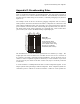
Figure D-4
Example Schematic and
Wiring Diagram
Schematic (left) and
wiring diagram (right)
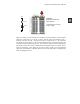
Here is a more complex example that involves two additional parts, a photoresistor and a
capacitor. The schematic symbols and part drawings for these components are shown in
Figure D-5.
0.01 µF
Figure D-5
Part Drawings and
Schematic Symbols
Photoresistor (top) and
non-polar capacitor (bottom)
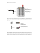
Since this schematic shown in Figure D-6 calls for a 220 Ω resistor, the first step is to
consult Appendix C: Resistor Color Codes to determine the color code for a 220 Ω
resistor. The color code is Red, Red, Brown. This resistor is connected to P6 in the
schematic, which corresponds to the resistor lead plugged into the socket labeled P6 in