
Robotics with the Boe-Bot text v2.2


Chapter 7: Navigating with Infrared Headlights · Page 243
P10
Vss
220
Ω
Red
LED
P1
Vss
220
Ω
Red
LED
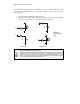
Figure 7-6
Left and Right
Indicator LEDs
Left IR Pair Right IR Pair
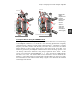
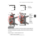
Figure 7-7
Wiring
Diagrams for
Red LED
Indicators
with IR Object
Detection
Circuits
Board of
Education
(left) and
HomeWork
Board (right).
Testing the System
There are quite a few components involved in this system, and this increases the
likelihood of a wiring error. That’s why it’s important to have a test program that shows
you what the infrared detectors are sensing. You can use this program to verify that all
the circuits are working before unplugging the Boe-Bot from its serial cable and testing
other objects.
Example Program – TestIrPairsAndIndicators.bs2
√ Reconnect power to your board.
√ Enter, save, and run TestIrPairsAndIndicators.bs2.
P15
P14
P13
P12
P11
P10
P9
P8
P4
P2
P1
P0
P7
P6
P5
P3
X2
X3
Vdd Vss Vin
Board of Education
© 2000-2003
Rev C
Vdd
Black
Red
X4 X5
15 14 13 12
To Servos
+
P15
P14
P11
P13
P12
P10
P9
P8
P4
P2
P1
P0
P7
P6
P5
P3
X2
X3
Vdd VssVin
Rev B
(916) 624-8333
www.parallax.com
www.stampsinclass.com
To Servos
+
HomeWork Board
Anode
leads
Anode
leads