
Robotics with the Boe-Bot text v2.2


Chapter 6: Light Sensitive Navigation with Photoresistors · Page 207
Vss
220
Ω
P6
0.01 µF
Vss
220
Ω
P3
0.01 µF
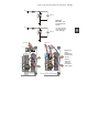
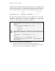
Figure 6-8
Schematic - Two
Photoresistor RC
Circuits
For measurement
of resistance that
varies with light.
P15
P14
P13
P12
P11
P10
P9
P8
P7
P5
P2
P1
P0
P6
P4
P3
X2
X3
Vdd VssVin
Board of Education
© 2000-2003
Rev C
Vdd
Black
Red
X4 X5
15 14 13 12
To S e rvos
+
P15
P14
P11
P13
P12
P6
P4
P3
P10
P9
P8
P7
P5
P2
P1
P0
X2
X3
Vdd VssVin
Rev B
(916) 624-8333
www.parallax.com
www.stampsinclass.com
To S er v o s
+
HomeWork Board
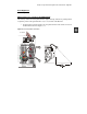
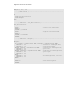
Figure 6-9
Wiring
Diagrams for
Photoresistor
Circuits
Board of
Education
(left) and
HomeWork
Board (right).