
Robotics with the Boe-Bot text v2.2


Chapter 3: Assemble and Test Your Boe-Bot · Page 97
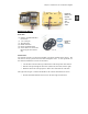
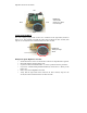
Figure 3-6
Battery Pack
Installed
Bottom view
(left);
top view
(right).
Mounting the Wheels
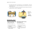
Parts List:
(1) Partially assembled Boe-Bot
(not shown)
(1) 1/16″ Cotter pin
(1) Tail wheel ball
(2) Rubber band tires
(2) Plastic machined wheels
(2) Screws that were saved in the
Removing the Servo Horns
step
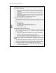
Figure 3-7
Wheel
Hardware
Instructions:
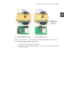
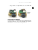
The left side of Figure 3-8 shows the Boe-Bot’s tail wheel mounted on the chassis. The
tail wheel is merely a plastic ball with a hole through the center. A cotter pin holds it to
the chassis and functions as an axle for the wheel.
√ Line the hole in the tail wheel up with the holes in the tail portion of the chassis.
√ Run the cotter pin through all three holes (chassis left, tail wheel, chassis right).
√ Bend the ends of the cotter pin apart so that it can’t slide back out of the hole.
The right side of Figure 3-8 shows the Boe-Bot’s drive wheels mounted on the servos.
√ Stretch each rubber band tire and seat it on the outer edge of each wheel.