
BOE-USB manual v1.4


Copyright © Parallax, Inc. • BOE-USB (#28850) • v1.4 7/20/2007 Page 4 of 5
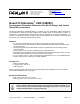
Using the Board of Education USB Breadboard
The breadboard has many strips of copper which run underneath the board
These strips connect the sockets to each other horizontally, in groups of 5.
This makes it easy to connect components together to build circuits.
Each metal strip and its five sockets forms a node. A node is a point in a
circuit where two components are connected. Connections between different
components are formed by putting their legs in a common node. To use the
breadboard, the legs of components or wires are placed in the sockets. The
sockets are made so that they will hold the component in place. For chips
with many legs (ICs), place them in the middle of the board so that half of the
legs are on the left side and half are on the right side. Nodes on the left side
are not connected to nodes on the right side.
X3
Vdd
VssVin
P15
P14
P13
P12
P11
P10
P9
P8
P7
P6
P5
P4
P3
P2
P1
P0
X2
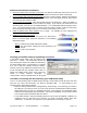
Example Circuit
On the left is a simple circuit used to monitor light levels. The illustration on the right shows how this
circuit can be constructed on the BOE-USB breadboard.
P0
220
Ω
Vss
0.1 µF
Vdd
P15
P14
P13
P12
P11
P10
P9
P8
P7
P6
P5
P4
P3
P2
P1
P0
X2
X3
Vdd
VssVin
' Adapted from "What's a Microcontroller" v2.2" example program
' TestPhotoresistor.bs2 from www.parallax.com
' {$STAMP BS2}
' {$PBASIC 2.5}
time VAR Word
DO
HIGH 2
PAUSE 100
RCTIME 0, 1, time
DEBUG HOME, "time = ", DEC5 time
LOOP
Board Revisions and the Stamps in Class Series
All revisions of the Board of Education USB are functionally equivalent to the serial Board of Education
Rev C. When using the BOE-USB with titles in the Stamps in Class series, follow the directions given for
the Board of Education Rev C. Do not follow the directions given for the serial Board of Education Rev A
or Rev B.