
BOE-USB manual v1.4


Copyright © Parallax, Inc. • BOE-USB (#28850) • v1.4 7/20/2007 Page 2 of 5
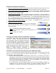
Power Supply Clip and Barrel Jack (top left): The 9 V battery clip and the barrel jack are positioned so
that they cannot be accidentally used at the same time. For the jack we recommend our 9 VDC V 300 mA
supply, # 750-00008.
Power Switch (bottom center): The leftmost position (0) is OFF – all power is disconnected. Always
place the switch in position-0 when changing components on the breadboard, and when disconnecting or
reconnecting to the PC. The middle position (1) provides Vin to the regulator, the BASIC Stamp IC
socket, and to the connectors marked Vin. In this position, Vdd will also be available on the breadboard
and AppMod (see below) connectors. The rightmost position (2) provides power to the servo connectors
X4 and X5 (see servo power selection below). The three-position position power switch is convenient
when using the BOE-USB on small robots, like the Parallax Boe-Bot
®
. Use position 1 to edit and test
code while power is removed from the servos.
Servo Ports (X4 and X5), and Power Selection (top right): Select the power provided to servo sockets
X4 and X5 by the jumper located between them; the default position is Vdd (+5 V regulated). When using
a six-volt battery pack (as on a Boe-Bot robot), you may wish to move this jumper to the Vin position to
provide extra power to the servos. When using Vin in the servo ports, always check to make sure the
voltage supplied does not exceed the specifications of the particular brand of servos you are using. X4
and X5 connect to the BASIC Stamp I/O pins labeled above the sockets; do not build incompatible circuits
connected to the same I/O pins on the breadboard when using X4 or X5. Always check the pinout and
voltage requirements of 3-pin devices before connecting them to X4 or X5.
Reset Button: The reset button can be used to restart your BASIC Stamp IC without having to cycle the
power. This saves wear-and-tear on the power switch for simple program restarts.
Breadboard Access for BASIC Stamp I/O (X2), Vdd, Vin, and Vss (X3): The BASIC Stamp IC’s 16 I/O
pins are brought to the X2 female socket left of the breadboard. I/O pins are accessed by plugging wires
into the header, then into the breadboard sockets. The X3 socket provides four connection points for a
+5V (Vdd) connection, unregulated input voltage (Vin), and ground (Vss).
AppMod Header (X1): provides connection and signal routing for 20-pin AppMods, the eb500
EmbeddedBlue Transceiver (#30068) and the LCD Terminal (#29121). All I/O pins, Vdd, Vin, and Vss
are routed through the AppMod connector. The BASIC Stamp I/O pins used by a device in the AppMod
Header should not also be used with conflicting circuits on the breadboard area. Please refer to the
individual AppMod product documentation for device pin maps.