
RFID Reader documentation v2.1

Copyright © Parallax Inc. RFID Card Reader Serial & USB (#28140 / 28340) v2.1 8/28/2008 Page 3 of 11
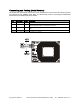
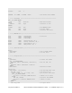
Connecting and Testing (Serial Version)
The Parallax RFID Card Reader serial version can be integrated into any microcontroller design using only
four connections (VCC, /ENABLE, SOUT, GND). Use the following circuit for connecting the Parallax RFID
Card Reader to the BASIC Stamp microcontroller.
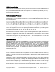
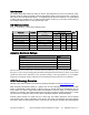
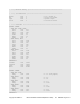
Pin Pin Name Type Function
1 VCC P System power, +5V DC input.
2 /ENABLE I
Module enable pin. Active LOW digital input. Bring this pin LOW to
enable the RFID reader and activate the antenna.
3 SOUT O
Serial Output TTL-level interface, 2400bps, 8 data bits, no parity, 1 stop
bit.
4 GND G System ground. Connect to power supply’s ground (GND) terminal.
Note: Type: I = Input, O = Output, P = Power, G = Ground