
RFID Reader documentation v2.1

Copyright © Parallax Inc. RFID Card Reader Serial & USB (#28140 / 28340) v2.1 8/28/2008 Page 2 of 11
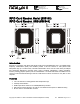
RFID Compatibility
The Parallax RFID Card Reader works exclusively with the EM Microelectronics-Marin SA EM4100-family of
passive read-only transponder tags at 125 kHz. A variety of different tag types and styles exist with the
most popular made available from Parallax. Each transponder tag contains a unique identifier (one of 2
40
,
or 1,099,511,627,776 possible combinations) that is read by the RFID Card Reader and transmitted to the
host via a simple serial interface.
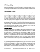
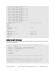
Communication Protocol
When the RFID Card Reader is active and a valid RFID transponder tag is placed within range of the
activated reader, the unique ID will be transmitted as a 12-byte printable ASCII string serially to the host
in the following format:
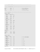
Unique ID
Digit 1
MSB
LSB
Start Byte
(0x0A)
Unique ID
Digit 2
Unique ID
Digit 3
Unique ID
Digit 4
Unique ID
Digit 5
Unique ID
Digit 6
Unique ID
Digit 7
Unique ID
Digit 8
Unique ID
Digit 9
Unique ID
Digit 10
Stop Byte
(0x0D)
The start byte and stop byte are used to easily identify that a correct string has been received from the
reader (they correspond to a line feed and carriage return characters, respectively). The middle ten bytes
are the actual tag's unique ID. For example, for a tag with a valid ID of 0F0184F07A, the following bytes
would be sent: $0A, $30, $46, $30, $31, $38, $34, $46, $30, $37, $41, $0D
All communication is 8 data bits, no parity, 1 stop bit, and least significant bit first (8N1). The baud rate is
configured for 2400 bps, a standard communications speed supported by most any microprocessor or PC,
and cannot be changed. The Parallax RFID Card Reader initiates all communication. Output from the
serial RFID Card Reader TTL level non-inverted. The USB version of the RFID Card Reader handles serial
communications through the VCP (virtual COM port) driver. This allows easy access to the serial data
stream from any programming language that can open a COM port.
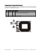
Interface Details
The RFID Card Reader is activated via the /ENABLE line. When the RFID Card Reader is powered and the
/ENABLE line is pulled HIGH, the module will be inactive (standby mode) and the LED will be GREEN.
When the /ENABLE line is pulled LOW, the RFID Card Reader enter its active state and enable the
antenna to interrogate for tags. The current consumption of the module will increase dramatically when
the module is active. On the serial version of the RFID Card Reader the /ENABLE line is directly
accessible via the 4-pin header. On the USB version this line is controlled by the COM port DTR line.
Enabling DTR will activate the RFID Card Reader (LED Red) while disabling DTR will deactivate the RFID
Card Reader (LED Green).
A visual indication of the state of the RFID Card Reader is given with the on-board LED. When the
module is successfully powered-up and is in an idle state, the LED will be GREEN. When the module is in
an active state and the antenna is transmitting, the LED will be RED. The LED can be used to visually
indicate to a user that the tag has been read successfully by deactivating the reader briefly when the tag
has been read.
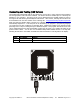
The face of the RFID tag should be held parallel to the front or back face of the antenna (where the
majority of RF energy is focused). If the tag is held sideways (perpendicular to the antenna) you may
have difficulty getting the tag to be read. Only one transponder tag should be held up to the antenna at
any time. The use of multiple tags at one time will cause tag collisions and confuse the reader. The tags
available in the Parallax store have a read distance of approximately 3 inches. Actual distance may vary
slightly depending on the size of the transponder tag and environmental conditions of the application.