
QTI line follower appkit documentation v2.0

Copyright © Parallax Inc. QTI LIne Follower AppKit (#28108) v2.0 3/23/2009 Page 5 of 6
' {$STAMP BS2}
' {$PBASIC 2.5}
' CheckQtiSubroutine.bs2
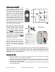
' Displays QTI sensor states. 0 means white surface, 1 means
' black.
qtis VAR Nib ' qti black/white states
OUTB = %1111 ' Set OUTB bits to 1
DEBUG CRSRX, 8, "FMMF", CR, ' Display bit positions
CRSRX, 8, "LLRR", CR
DO ' Main DO...LOOP
GOSUB Check_Qtis ' Get QTI states
DEBUG BIN4 ? qtis, CRSRUP ' Display QTI states
PAUSE 100 ' 1/10 s delay
LOOP
Check_Qtis:
' Result -> qtis variable. 0 means white surface, 1 means
' black surface.
DIRB = %1111 ' P7..P4 -> output
PAUSE 0 ' Delay = 230 us
DIRB = %0000 ' P7..P4 -> input
PAUSE 0 ' Delay = 230 us
qtis = INB ' Store QTI outputs in INB
RETURN
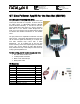
The BASIC Stamp has a variety of parallel I/O control features that make it possible to perform
operations on groups of I/O pins. CheckQtiSubroutine.bs2 uses the BASIC Stamp's
DIRB and OUTB
variables to control the directions and output states of the I/O pins P7, P6, P5, and P4. When these I/O
pins are set to input with
DIRB = %0000, the program also takes a snapshot of the binary states these
I/O pins sense as a result of the four QTIs' R pin voltages with the command
qtis = INB.
Simple Line-Following
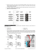
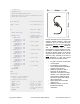
LineFollowWithCheckQtis.bs2 is designed to start following a line as soon as you place a QTI over the
electrical tape. It will stop line following as soon as it runs out of electrical tape. Start with an easy
course, like a large S shape as shown below. If the QTIs passed the "Testing for Line Detection" tests, it
should navigate the course with ease.
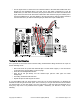
√ Enter and run LineFollowWithCheckQtis.bs2.
√ Place the Boe-Bot on the course so that in straddles the line with the mid left and mid right QTIs
over the electrical tape.
If your QTIs’ cables are reversed, the Boe-Bot will appear to try to jump off the line at the first
opportunity. Otherwise, it should faithfully follow the line until it reaches the end of the tape.