
QTI line follower appkit documentation v2.0

Copyright © Parallax Inc. QTI LIne Follower AppKit (#28108) v2.0 3/23/2009 Page 3 of 6
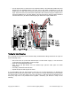
4. Attach a QTI sensor to the other end of each threaded standoff, using a 3/8-inch screw. The
sensors should be facing downwards, and the 3-pin headers on each sensor should be pointing
towards the back of the chassis.
5. If necessary, slightly loosen the 7/8-inch screws and adjust the position of the QTI sensors so
that they are closely positioned edge to edge.
6. Tighten all connections securely.
.
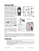
Building the Sensing Circuits
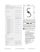
Each QTI B pin is tied to Vss (ground) and each W pin is connected to Vdd (5 V). R pin connects to a
BASIC Stamp I/O pin:
Far right to P4
Mid right to P5
Mid left to P6
Mid right to P7
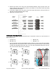
√ Use the schematic and the wiring diagram below to build the circuits for the three-pin headers.
Although there are many ways this circuit can be built, the setup shown below is useful because
it's thrifty with breadboard real-estate. Also, if you are using a HomeWork Board with your Boe-
Bot, it won’t interfere with the servo connections.