
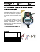
QTI line follower appkit documentation v2.0

Copyright © Parallax Inc. QTI LIne Follower AppKit (#28108) v2.0 3/23/2009 Page 2 of 6
A Closer Look at the QTI
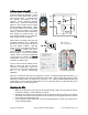
The QTI module is designed for close
proximity infrared (IR) detection. Take a
look at the small square black box just
above the QTI label. It’s nested below
the capacitor and between the two
resistors. That’s a QRD1114 reflective
object sensor. There’s an infrared diode
behind its clear window and an infrared
transistor behind its black window. When
the infrared emitted by the diode reflects
off a surface and returns to the black
window, it strikes the infrared transistor’s
base, causing it to conduct current. The
more infrared incident on the transistor’s
base, the more current it conducts.
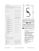
When used as an analog sensor, the QTI
can detect shades of gray on paper and
distances over a short range if the light in
the room remains constant. With this
circuit, you can set P3 high and then test
it with
RCTIME to measure how long it
takes the capacitor to discharge through
the IR transistor. Since the IR transistor
conducts more or less current depending
on how much IR it receives, the
RCTIME
measurement can give you an indication
of distance or shade of gray.
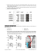
If all you want to know is whether a line is
black or white, the QTI can also be
converted to a digital sensor. This is how
the array of four QTI sensors will be used
later in our Boe-Bot line-following
application.
When W is connected to Vdd and B is connected to Vss, the R terminal’s voltage will drop below 1.4 V
when the IR transistor sees infrared reflected from the IR LED. When the IR LED’s signal is mostly
absorbed by a black surface, the voltage at R goes above 1.4 V. Since the BASIC Stamp interprets any
voltage above 1.4 V as 1 and any voltage below 1.4 V as 0, this circuit gives us a quick and easy way to
detect a black line on a white background.
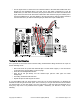
Mounting the QTIs
1. Match the components in your kit to the Kit Contents above to make sure all pieces are present.
If anything is missing, contact Parallax Tech Support.
2. Referring to the picture on the next page, insert the 7/8-inch screws through the top of the Boe-
Bot chassis, at the three slots near the front. Two screws will go through the center slot, and one
screw each in the right and left slots.
3. On the underside of the chassis, slip a 1/2-inch unthreaded spacer on each screw, followed by a
1-inch threaded standoff.
' AnalogQti.bs2
' {$STAMP BS2}
' {$PBASIC 2.5}
time VAR word
DO
HIGH 3
RCTIME 3, 1, time
DEBUG CLS, ? time
PAUSE 100
LOOP
Vdd = 5 VCD
Vss = 0 V (ground)