
2-Axis Joystick Documentation v1.1

Copyright © Parallax Inc. 2-Axis Joystick (#27800) v1.1 5/13/2010 Page 2 of 3
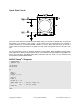
Quick Start Circuit
This circuit works with the code below for the BASIC Stamp 2 to provide an RCTIME value for each axis
that relates to the position of the joystick. In this manner the two potentiometers are providing a
variable resistance for use with the RCTIME command. Caution: When using this circuit, do not use a
resistor value less than 220 Ω and do not apply more than 5 VDC through this resistor to the L/R or U/D
pins.
For more information on how to measure resistance using the BASIC Stamp RCTIME command, please
read Chapter#5 of
What’s a Microcontroller?
book, a free downlaod at www.parallax.com/go/WAM. The
PDF is also included in the BASIC Stamp Editor software’s Help file, which is a free download from
www.parallax.com/basicstampsoftware.
BASIC Stamp
®
2 Program
' {$STAMP BS2}
' {$PBASIC 2.5}
LR VAR Word
UD VAR Word
DO
HIGH 4
PAUSE 2
RCTIME 4, 1, UD
HIGH 11
PAUSE 2
RCTIME 11, 1, LR
DEBUG HOME, "UD = ", DEC UD, CLREOL, CR,
"LR = ", DEC LR, CLREOL
PAUSE 50
LOOP