
Installation Manual


5300 Series 120/240VAC Wiring
1. Horizontal Mounting Only! Mount the 5300 Series to a
vertical surface with the front of the control center open to
the living area of the RV. Leave adequate space behind
unit for ventilation and wire routing.
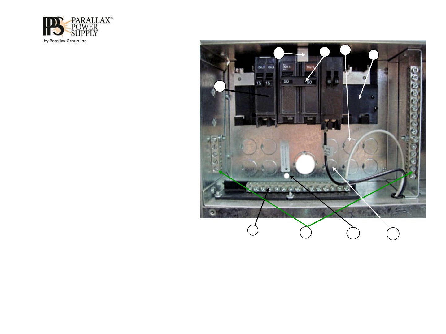
2. Panel rated 120/240V 50 Ampere. Supports a
maximum of twelve 120VAC branch circuits (Circuit
breakers not supplied). See AC wiring label for a list of
suitable main and branch load circuit breakers. Use
suitable filler plates for any unused breaker locations.
3. Install appropriately sized strain relief to provide wire
support on all AC or DC Chassis knockouts removed.
4. 120 VAC load breakers amperage rating chosen by AWG
wire size used for the load. Connect to (black) load circuit
“hot” leads. #14 AWG “Romex” connect to maximum 15
ampere load breaker. #12 AWG “Romex” connect to a
maximum 20 ampere load breaker.
5. Connect Shore power “line” conductors (black, red) to a 2-
pole 50 ampere maximum main breaker.
6. NEC requires breaker “hold-down” bracket to secure
the 50 ampere 2-pole main breaker.
7. Shore power and 120 VAC load circuit (white) neutrals
(commons) connect to this isolated terminal bar.
8. Shore Line (green conductor) and 120 VAC load circuit
bare copper grounds and bonding conductor may only
connect to these terminal bars.
9. AC bond routing hole for (# 8 AWG minimum required)
AC bonding conductor.
10. Connect converter power “hot” (black) line conductor wire
pin to a 20 ampere (maximum) branch load breaker.
11. Refer to breakers and AC wiring label for terminal bar
and circuit breaker torque ratings..
4
6
7
8
2
9
10
5
3
Product shown with Door and dead front plate removed.
Note- Circuit breakers not supplied with unit.
DANGER! HAZARD OF ELECTRICAL SHOCK OR BURN. TURN OFF
POWER SUPPLY FOR THIS EQUIPMENT BEFORE WORKING INSIDE.
DANGER! RISQUE DE CHOC ÉLECTRIQUE OU DE BRÛLURE.
COUPEZ L'ALIMENTATION DE CET ÉQUIPEMENT AVANT DE
TRAVAILLER À L'INTÉRIEUR.
6