FrameSaver® DSL 9783 Router Installation Instructions Document Number 9783-A2-GN11-10 April 2001 Contents FrameSaver DSL 9783 Router Overview ...................................................... 1 Upgrading a Basic Unit to SLV ...................................................................... 3 Product Documentation Online ..................................................................... 3 Package Checklist ....................................................................................
The router has an SDSL front end and is a manageable frame relay aware endpoint. It operates as a bridge or an IP router that connects a DSL link to an Ethernet network. The FrameSaver DSL 9783 Router is used for data only and provides corporate LAN access over traditional twisted-pair copper telephone wiring. Copper pairs run from the central office (CO) to the customer premises (CP) to create the local loop.
Refer to About FrameSaver DSL Devices in the User’s Guide for a list of FrameSaver DSL 9783 features, and the capabilities provided by each feature set. Upgrading a Basic Unit to SLV A basic FrameSaver DSL 9783 Router can be upgraded to full SLV capability at any time by ordering a FrameSaver SLV Activation Certificate. A certificate can be ordered for a single 9783 router, or for many 9783 routers. The OpenLane® SLM system, Release 5.
Wiring and Cables You May Need The following wiring and cables are used with this product, which uses standard interface connectors: ❑ Standard connectors: An 8-pin modular (similar to RJ48C) or 6-pin modular (similar to RJ11) wall jack for the DSL network connection. ❑ DSL wiring: Unshielded twisted-pair wiring (CAT3, or better). The CAT3 wiring must meet EIA/TIA-568 specifications with 24 AWG (.5 mm) or 26 AWG (.4 mm). ❑ Ethernet wiring: Shielded twisted-pair wiring (CAT5, or better).
Prior to Installing the Router These Installation Instructions assume that the virtual circuits at the DSLAM have already been configured. Provisioning of these circuits can be simplified by using the OpenLane SLM (Service Level Management) system, as indicated in Provisioning Data Circuits in OpenLane.
Installing the Router Place the FrameSaver DSL 9783 Router on a flat surface, with clearance for the rear connectors. Procedure 1. Use the supplied 8-pin DSL network cable (for use in the U.S.), or a 6-pin DSL network cable (using connectors similar to RJ11), as applicable, for the DSL connection. Insert one end of the cable into the jack labeled NET on the router. Insert the other end into the wall jack for DSL data communications.
3. Use an 8-pin Ethernet cable for the Ethernet connection. Insert one end of the cable into the jack labeled ETHERNET. — Use a straight-through cable to connect the other end of the cable to an Ethernet hub. Do not connect to the hub’s optional Uplink connection with a straight-through cable; the Uplink connection requires an Ethernet crossover cable.
4. Use a VT100-compatible asynchronous terminal or PC to set up management access to the unit. Insert the DB25 end of the EIA-232 cable into the router’s COM port. Tighten the screws on each side of the connector. Insert the other end into the terminal or PC. The terminal or PC’s configuration must be compatible with the router’s. Refer to the procedure on page 13 of Configuration Setup. If connecting an external modem to the COM port, refer to Connecting an External Modem on page 23.
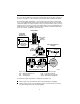
5. Insert the supplied power cord’s round end into the jack labeled POWER. Plug the transformer into an AC outlet. Install the supplied tie wrap for strain relief, as shown. Grounded Power Outlet Tie Wrap Power Jack POW ER COM ETHE RNET NET OOK K AATT MM DDS SLL OO KK AALL MM TTEE SSTT 9783-C 9783 ROUTER R R DSL FrameSaver ®® SLV TM SDSL System Port Port Network 01-16877-01 Installation of the hardware is now complete.
Status LEDs After a successful self-test, the LEDs should appear as indicated in BOLD in the Condition column below. LED Condition Status System LEDs OK ON The router has power. ALM ON An alarm condition exists. OFF No alarms have been detected by the router. ON The router is performing the power-on self-test, or a test initiated by the service provider is currently active. OFF No tests are active. TEST Network LEDs ATM DSL ON – Green ATM mode is active and cell delineation is in sync.
Troubleshooting LED Symptom Action All LEDs are on. If the LEDs remain on for more than ten minutes, the router is not functional. Unplug the router and reapply power. If the ALM LED is still on, contact the service provider. ALM LED only remains on. The power-on self-test may have failed. Unplug the router and reapply power. If the alarm LED is still on, contact the service provider. ALM and TEST LEDs are blinking. Firmware download may be in progress.
Configuration Setup Once the router is installed, it can be accessed locally through the menu-driven user interface via an asynchronous terminal or PC connection, or remotely via a Telnet session, and the router’s interfaces can be provisioned.
Procedure To access the menu-driven user interface: 1. Verify the terminal or PC’s configuration: — Data Rate is set to 19.2 kbps. — Character Length is set to 8 data bits. — Parity is set to None. — Stop Bits is set to 1. — Flow Control is set to None. 2. Press Enter to display the Main Menu.
Menu Navigation The router should operate using the default (factory-set) configuration options. Refer to the following table for help in navigating the menus. Press the . . . To . . . Esc key Go back one screen or menu level. For a visual display of the menu hierarchy, see the Quick Reference. Tab key, and Up (↑), Down (↓ ), Left (←), Right (→) Arrow keys Move the cursor from one menu item to the next. Enter or Return key Complete the menu or option selection.
Verifying that Self-Test Passed To verify that the unit passed its self-test, go to the System and Test Status screen. Main Menu → Status → System and Test Status The results of the self-test appear directly under the screen title. If any failure messages appear, reset the unit by disconnecting, then reconnecting the power cord. The unit will perform the self-test again. If the failure reappears, call your service representative for assistance.
2. If the router will not be connected to a Paradyne DSLAM, change the DSLAM Type. Other selections are Alcatel (NewBridge), PairGain, and Nokia. 3. Enter the Node IP Address and Subnet Mask. 4. Specify TS Access if a Troubleshooting (TS) DLCI or Virtual Circuit (VC) is being set up for remote access by the service provider. The default is 0,35. 5. Select Create a Dedicated Network Management Link to set up for permanent remote access by the NOC. Enter a DLCI, VPI, and VCI at the resulting prompts. 6.
Configuring SNMP Trap Managers and Traps Procedure To enter SNMP managers and configure traps: 1. Select SNMP Traps. Main Menu → Configuration → Management and Communication → SNMP Traps 2. Configure the following: — Enable SNMP Traps. — Identify the total Number of Trap Managers. — Specify the IP address for each NMS Trap Manager to which traps will be sent. — Specify the Initial Route Destination for each Trap Manager. The default is AutoRoute. — Select or disable trap categories, as needed. 3.
Procedure 1. Create a DLCI on the router virtual port. Configuration → Virtual Router Ports → DLCI Records Assign the DLCI number that will be used for management on Serial port 0 (Rtr-S0 – e.g., DLCI 900). 2. Create a management PVC using the DLCI just configured on Serial port 0 to connect the management link to the router.
Verifying the End-to-End Management Path After installation of a remote router, run an ATM Ping test from the Hotwire® GranDSLAM. Procedure To Ping the router: 1. From the Hotwire ATM Line Card’s Main Menu, select the ATM Ping test. Diagnostics → ATM Ping (D-C) 2. Enter a VPI of 0 and a VCI of 35. 3. Select a Direction of Endpoint, then Start. 4. If the test is successful, select a Direction of Network, then Start. If both tests are successful, the VC has been tested from end to end.
Checking PVC Connections Check PVC connections to verify that all PVCs, including management PVCs, are configured and active. Procedure To verify PVCs: 1. Select PVC Connection Status from the Status menu. The PVC Connection Status screen shows all PVC connections, the interface source and DLCI number of the incoming data linked to the interface, and DLCI number for the outgoing data. You can also see whether the PVC is active. 2. Verify that each PVC is active.
Cables and Connectors Refer to Installing the Router on page 6 for cable installation information. The DSL network interface uses an 8-pin, un-keyed modular plug. Use a standard twisted-pair CAT3, or better, cable.
The Ethernet interface connector uses an 8-pin, non-keyed modular plug. Use shielded twisted-pair CAT5, or better, cables. See Step 3 on page 7. — To connect the router to an Ethernet hub, use a straight-through connection.
The communication (COM) port connector uses a 25-position, EIA-232-C connector.
DSL Router Technical Specifications Item Specification* Approvals FCC Part 15 Class A digital device Safety Certifications Refer to equipment’s label for approvals on product Physical Environment Operating temperature 32°F to 122°F (0°C to 50°C) Storage temperature –4°F to 158°F (–20°C to 70°C) Relative humidity 5% to 85% (noncondensing) Shock and vibration Withstands normal shipping and handling Power Consumption and Dissipation 4.5 watts, 60 Hz ±3, 0.135 A at 120 VAC ±12 Result: 15.
! Important Safety Instructions 1. Read and follow all warning notices and instructions marked on the product or included in the manual. 2. Slots and openings in the cabinet are provided for ventilation. To ensure reliable operation of the product and to protect it from overheating, these slots and openings must not be blocked or covered. 3. Do not allow anything to rest on the power cord and do not locate the product where persons will walk on the power cord. 4.
CE Marking When the product is marked with the CE mark on the equipment label, this demonstrates full compliance with the following European Directives: Directive 73/23/EEC – Council Directive of 19 February 1973 on the harmonization of the laws of the member states relating to electrical equipment designed for use within states relating to electrical equipment designed for use within certain voltage limits, as amended by Directive 93/68/EEC.
Government Requirements Certain governments require that instructions pertaining to connection to the telephone network be included in the installation and operation manual. Specific instructions are listed in the following sections. Notice to Users of the Canadian Telephone Network The Industry Canada label identifies certified equipment.
Warranty, Sales, Service, and Training Information Contact your local sales representative, service representative, or distributor directly for any help needed. For additional information concerning warranty, sales, service, repair, installation, documentation, training, distributor locations, or Paradyne worldwide office locations, use one of the following methods: Internet: Visit the Paradyne World Wide Web site at www.paradyne.com. (Be sure to register your warranty at www.paradyne.com/warranty.