
User's Manual
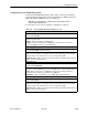
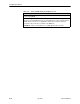


Table Of Contents
- Contents
- About This Guide
- About the FrameSaver DSL Unit
- User Interface and Basic Operation
- Configuration Procedures
- Configuration Options
- Overview
- Using the Easy Install Feature
- Setting Up So the Router Can Receive RIP
- Entering System Information and Setting the System Clock
- Configuration Option Tables
- Configuring the Overall System
- Configuring the Physical Interfaces
- Configuring Frame Relay for the Data Port
- Configuring ATM for the Network Interface
- Configuring Circuit and DLCI Records
- Configuring PVC Connections
- Setting Up Management and Communication Options
- Configuring Node IP Information
- Configuring Management PVCs
- Configuring General SNMP Management
- Configuring Telnet and/or FTP Session Support
- Configuring SNMP NMS Security
- Configuring SNMP Traps
- Configuring the Ethernet Port
- Configuring the Communication Port
- Configuring the COM Port to Support an External Modem
- Security and Logins
- Operation and Maintenance
- FTP Operation
- Troubleshooting
- Setting Up OpenLane for FrameSaver Devices
- Setting Up Network Health for FrameSaver Devices
- Menu Hierarchy
- SNMP MIBs and Traps, and RMON Alarm Defaults
- Connectors, Cables, and Pin Assignments
- Technical Specifications
- Equipment List
- Index

Configuration Options
4-40
9783-A2-GB20-00
July 2000
Configuring the Ethernet Port
Select Ethernet Port from the Management and Communication menu to
configure the Ethernet port (see Table 4-17).
Main Menu
→
Configuration
→
Management and Communication
→
Ethernet Port
Table 4-17. Ethernet Port Options (1 of 2)
Interface Status
Possible Settings: Enable, Disable
Default Setting: Enable
Determines whether the Ethernet port is being used and can be configured.
Enable – The port is active. It can receive Version 2 or IEEE 802.3 MAC frames, or
transmit Version 2 MAC frames only.
Disable – The port is not active. When the port is disabled, the following will occur:
H No alarms or traps configured for the port will be generated.
H All port uses that refer to the Ethernet port, like the Default IP Destination and
Initial Route Destination, will be reset to their default values (see Table 4-11, Node
IP Options, and Table 4-16, SNMP Trap Options).
IP Address
Possible Settings: 001.000.000.000 – 223.255.255.255, Clear
Default Setting: Clear (000.000.000.000)
Specifies the IP address needed to access the Ethernet port.
001.000.000.000 – 223.255.255.255 – Shows the IP address for the port, which can be
viewed or edited.
Clear – Fills the IP address with zeros.
Subnet Mask
Possible Settings: 000.000.000.000 – 255.255.255.255, Clear
Default Setting: 000.000.000.000
Specifies the subnet mask associated with the IP address that is needed to access the
Ethernet port.
000.000.000.000 – 255.255.255.255 – Set the Ethernet port’s subnet mask. The range
for each byte is 000 to 255.
Clear – Fills the subnet mask associated with the IP address with zeros.
Default Gateway Address
Possible Settings: 001.000.000.000 – 223.255.255.255, Clear
Default Setting: Clear (000.000.000.000)
Specifies the IP address for the port’s default gateway. It is used for packets that do not
have a route.
001.000.000.000 – 223.255.255.255 – Shows the IP address for the port, which can be
viewed or edited (i.e., a router on the LAN).
Clear – Fills the default gateway’s IP address with zeros.