
User's Manual


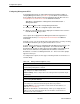

Table Of Contents
- Contents
- About This Guide
- About the FrameSaver DSL Unit
- User Interface and Basic Operation
- Configuration Procedures
- Configuration Options
- Overview
- Using the Easy Install Feature
- Setting Up So the Router Can Receive RIP
- Entering System Information and Setting the System Clock
- Configuration Option Tables
- Configuring the Overall System
- Configuring the Physical Interfaces
- Configuring Frame Relay for the Data Port
- Configuring ATM for the Network Interface
- Configuring Circuit and DLCI Records
- Configuring PVC Connections
- Setting Up Management and Communication Options
- Configuring Node IP Information
- Configuring Management PVCs
- Configuring General SNMP Management
- Configuring Telnet and/or FTP Session Support
- Configuring SNMP NMS Security
- Configuring SNMP Traps
- Configuring the Ethernet Port
- Configuring the Communication Port
- Configuring the COM Port to Support an External Modem
- Security and Logins
- Operation and Maintenance
- FTP Operation
- Troubleshooting
- Setting Up OpenLane for FrameSaver Devices
- Setting Up Network Health for FrameSaver Devices
- Menu Hierarchy
- SNMP MIBs and Traps, and RMON Alarm Defaults
- Connectors, Cables, and Pin Assignments
- Technical Specifications
- Equipment List
- Index

Configuration Options
4-28
9783-A2-GB20-00
July 2000
Configuring Management PVCs
Select Management PVCs to define inband management links by adding or
changing Management PVCs (see Table 4-12). First, DLCI records must have
been configured for the interface where the Management PVC will reside. See
Configuring Circuit and DLCI Records
for additional information.
Main Menu
→
Configuration
→
Management and Communication
→
Management PVCs
Select New or Modify to add or change Management PVCs.
H When you select N
ew, the configuration option field is blank.
H When you select Mo
dify, the values displayed for all fields are based on the
PVC ID number that you specified.
These options do not apply when the Management PVC is designated as a
TS Management Link (see
Configuring Node IP Information
for additional
information).
From this screen, you can go directly to the PVC Connections screen by selecting
the PVCC
onn function key for easy movement between screens.
Select the Del
ete function key, a Management PVC ID#, and respond Yes to the
Remove otherwise unused components associated with the
deleted PVC? prompt for quick removal of unused DLCIs. If the Management
PVC selected is defined as a trap Initial Route Destination, a Default IP
Destination, or a TS Access Management Link, an ... Are You Sure? prompt
appears to warn you.
To configure these options, Service Type on the Easy Install screen must be set
to Frame Relay.
Table 4-12. Management PVC Options (1 of 3)
Name
Possible Settings:
ASCII Text Entry
Default Setting: Initially blank; no default.
Specifies a unique name for the management PVC as referenced on screens
(e.g., Tampa for the Tampa, Florida office).
ASCII Text Entry –
Enter a unique name for the management PVC (maximum length
8 characters).
Intf
IP Address
Possible Settings: Node-IP-Address, Special
(
nnn
.
nnn
.
nnn
.
nnn
)
Default Setting: Node-IP-Address
Specifies the IP address needed to access the unit via this management PVC, providing
connectivity to an external IP network through the frame relay network.
Node-IP-Address – Uses the IP address contained in the Node IP Address (see
Table 4-11, Node IP Options).
Special (001.000.000.000 – 223.255.255.255) – Allows you to display/edit an IP
address for the unit’s management PVC when the IP address for this interface is
different from the node’s IP address.