
User's Manual


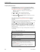

Table Of Contents
- Contents
- About This Guide
- About the FrameSaver DSL Unit
- User Interface and Basic Operation
- Configuration Procedures
- Configuration Options
- Overview
- Using the Easy Install Feature
- Setting Up So the Router Can Receive RIP
- Entering System Information and Setting the System Clock
- Configuration Option Tables
- Configuring the Overall System
- Configuring the Physical Interfaces
- Configuring Frame Relay for the Data Port
- Configuring ATM for the Network Interface
- Configuring Circuit and DLCI Records
- Configuring PVC Connections
- Setting Up Management and Communication Options
- Configuring Node IP Information
- Configuring Management PVCs
- Configuring General SNMP Management
- Configuring Telnet and/or FTP Session Support
- Configuring SNMP NMS Security
- Configuring SNMP Traps
- Configuring the Ethernet Port
- Configuring the Communication Port
- Configuring the COM Port to Support an External Modem
- Security and Logins
- Operation and Maintenance
- FTP Operation
- Troubleshooting
- Setting Up OpenLane for FrameSaver Devices
- Setting Up Network Health for FrameSaver Devices
- Menu Hierarchy
- SNMP MIBs and Traps, and RMON Alarm Defaults
- Connectors, Cables, and Pin Assignments
- Technical Specifications
- Equipment List
- Index

Configuration Options
4-24
9783-A2-GB20-00
July 2000
Setting Up Management and Communication Options
The following options can be selected from the Management and Communication
menu:
H Node IP Options
H Management PVC Options
H General SNMP Management Options
H Telnet and FTP Sessions Options
H SNMP NMS Security Options
H SNMP Traps Options
H Ethernet Port Options
H Communication Port Options
H External Modem (COM Port) Options
Configuring Node IP Information
Select Node IP to display, add, or change the information necessary to support
general IP communications for the node (see Table 4-11). When deploying units
to remote sites, minimally configure the Node IP Address and Subnet Mask.
Main Menu
→
Configuration
→
Management and Communication
→
Node IP
This set of configuration options includes a Troubleshooting (TS) Management
Link feature to help service providers isolate device problems within their
networks. This feature allows Telnet or FTP access to the unit on this link.
Troubleshooting over this link is essentially transparent to customer operations.
No alarms or SNMP traps are generated to create nuisance alarms for the
customer.
TS_Management_Link is initially disabled in most models, but the link can be
enabled at any time. Any valid network Management PVC created on a standard
DLCI can be used. When enabled, a troubleshooting link can be accessed any
time the service provider requests access. An assigned security level can also
control access.
When a DLCI has been defined as the troubleshooting management link, the
link is identified in the status field at the bottom of the Management PVC Entry
screen with the Note: This PVC has been designated as the TS
Access Management Link message.
NOTE:
The unit may come from the factory with a TS Management PVC already
set up (e.g., 980).