
User's Manual


Table Of Contents
- Contents
- About This Guide
- About the FrameSaver DSL Unit
- User Interface and Basic Operation
- Configuration Procedures
- Configuration Options
- Overview
- Using the Easy Install Feature
- Setting Up So the Router Can Receive RIP
- Entering System Information and Setting the System Clock
- Configuration Option Tables
- Configuring the Overall System
- Configuring the Physical Interfaces
- Configuring Frame Relay for the Data Port
- Configuring ATM for the Network Interface
- Configuring Circuit and DLCI Records
- Configuring PVC Connections
- Setting Up Management and Communication Options
- Configuring Node IP Information
- Configuring Management PVCs
- Configuring General SNMP Management
- Configuring Telnet and/or FTP Session Support
- Configuring SNMP NMS Security
- Configuring SNMP Traps
- Configuring the Ethernet Port
- Configuring the Communication Port
- Configuring the COM Port to Support an External Modem
- Security and Logins
- Operation and Maintenance
- FTP Operation
- Troubleshooting
- Setting Up OpenLane for FrameSaver Devices
- Setting Up Network Health for FrameSaver Devices
- Menu Hierarchy
- SNMP MIBs and Traps, and RMON Alarm Defaults
- Connectors, Cables, and Pin Assignments
- Technical Specifications
- Equipment List
- Index
Configuration Options
4-23
9783-A2-GB20-00
July 2000
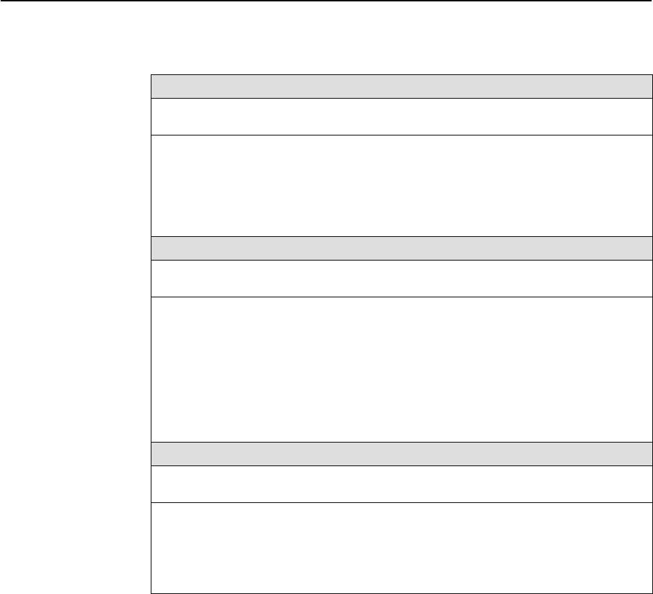
Table 4-10. PVC Connection Options (2 of 2)
Destination Link
Possible Settings: Net1-FR1
Default Setting: Initially blank; no default.
Specifies the frame relay interface used as the destination link; the to end of a from-to
link. The only valid settings for this configuration option are frame relay interfaces that
have at least one DLCI or EDLCI defined which are not part of a PVC connection or
management link. For example, if the network interface has no DLCIs defined, Net1-FR1
would not appear as a valid setting.
Net1-FR1 – Specifies the Network interface as the destination link.
Destination DLCI
Possible Settings: 16 – 1007
Default Setting: Initially blank; no default.
Specifies the destination DLCI for a frame relay interface. The DLCI must be defined
and cannot be part of a PVC connection or management link. For multiplexed DLCIs, at
least one EDLCI must be unconnected for the DLCI to be a valid selection.
NOTES: – Primary Destination DLCI has no value if Primary Destination Link
contains no value.
– For the basic feature set, only one EDLCI per multiplexed DLCI may be
used in the PVC connection.
16 – 1007 – Specifies the DLCI number.
Destination EDLCI
Possible Settings: 0 – 62
Default Setting: Initially blank; no default.
Specifies the destination Embedded Data Link Connection Identifier (EDLCI) for a frame
relay interface when a multiplexed DLCI record is selected as one end of a connection.
Display Conditions
– This option only appears when the Primary Destination DLCI
contains a multiplexed DLCI record number.
0 – 62 – Specifies the EDLCI number.