
User's Manual


Table Of Contents
- Contents
- About This Guide
- About the FrameSaver DSL Unit
- User Interface and Basic Operation
- Configuration Procedures
- Configuration Options
- Overview
- Using the Easy Install Feature
- Setting Up So the Router Can Receive RIP
- Entering System Information and Setting the System Clock
- Configuration Option Tables
- Configuring the Overall System
- Configuring the Physical Interfaces
- Configuring Frame Relay for the Data Port
- Configuring ATM for the Network Interface
- Configuring Circuit and DLCI Records
- Configuring PVC Connections
- Setting Up Management and Communication Options
- Configuring Node IP Information
- Configuring Management PVCs
- Configuring General SNMP Management
- Configuring Telnet and/or FTP Session Support
- Configuring SNMP NMS Security
- Configuring SNMP Traps
- Configuring the Ethernet Port
- Configuring the Communication Port
- Configuring the COM Port to Support an External Modem
- Security and Logins
- Operation and Maintenance
- FTP Operation
- Troubleshooting
- Setting Up OpenLane for FrameSaver Devices
- Setting Up Network Health for FrameSaver Devices
- Menu Hierarchy
- SNMP MIBs and Traps, and RMON Alarm Defaults
- Connectors, Cables, and Pin Assignments
- Technical Specifications
- Equipment List
- Index
Configuration Options
4-21
9783-A2-GB20-00
July 2000
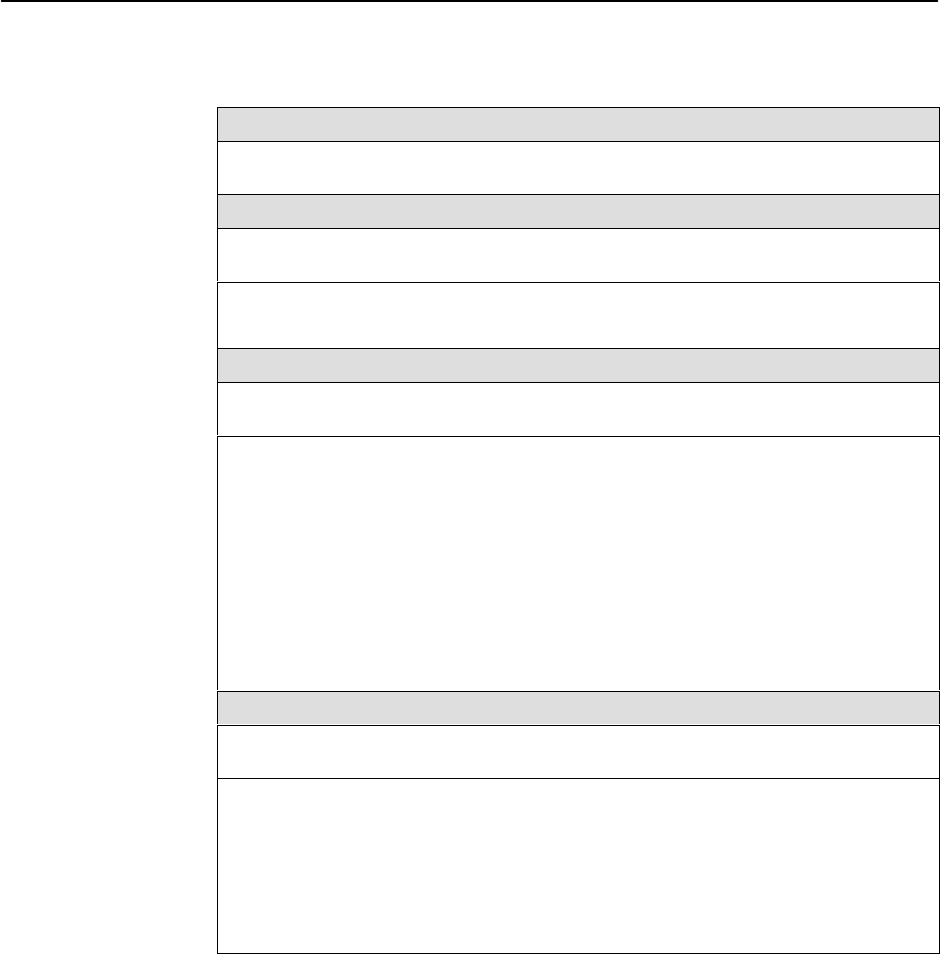
Table 4-9. DLCI Record Options (3 of 3)
Excess Burst Size (Bits)
Specifies the maximum amount of data in bits that the network may accept beyond the
CIR without discarding frames.
Be
Possible Settings: 0 – 2320000
Default Setting: 2256000
Allows you to display or change the DLCI’s excess burst size.
0 – 2320000 – Specifies the DLCI’s excess burst size.
DLCI Priority
Possible Settings: Low, Medium, High
Default Setting: High
Specifies the relative priority for data received on the DLCI from an attached device
(also known as
quality of service
). All data on Port 1 is cut-through, as long as there is
no higher-priority data queued from another user port. The DLCI priority set for an
interface applies to data coming into that interface. For example, the priority set for
DLCIs on Port 1 applies to data coming into Port 1 from the attached equipment (such
as a router).
Display Conditions
– This option is not available for the network interface.
Low – Data configured for the DLCI has low priority.
Medium – Data configured for the DLCI has medium priority.
High – Data configured for the DLCI has high priority.
Outbound Management Priority
Possible Settings: Low, Medium, High
Default Setting: Medium
Specifies the relative priority for management traffic sent on management PVCs on this
DLCI to the network.
Display Conditions
– This option is not available on a user data port.
Low – Management data configured for the DLCI has low priority.
Medium – Management data configured for the DLCI has medium priority.
High – Management data configured for the DLCI has high priority.