
User's Manual
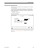


Table Of Contents
- Contents
- About This Guide
- About the FrameSaver DSL Unit
- User Interface and Basic Operation
- Configuration Procedures
- Configuration Options
- Overview
- Using the Easy Install Feature
- Setting Up So the Router Can Receive RIP
- Entering System Information and Setting the System Clock
- Configuration Option Tables
- Configuring the Overall System
- Configuring the Physical Interfaces
- Configuring Frame Relay for the Data Port
- Configuring ATM for the Network Interface
- Configuring Circuit and DLCI Records
- Configuring PVC Connections
- Setting Up Management and Communication Options
- Configuring Node IP Information
- Configuring Management PVCs
- Configuring General SNMP Management
- Configuring Telnet and/or FTP Session Support
- Configuring SNMP NMS Security
- Configuring SNMP Traps
- Configuring the Ethernet Port
- Configuring the Communication Port
- Configuring the COM Port to Support an External Modem
- Security and Logins
- Operation and Maintenance
- FTP Operation
- Troubleshooting
- Setting Up OpenLane for FrameSaver Devices
- Setting Up Network Health for FrameSaver Devices
- Menu Hierarchy
- SNMP MIBs and Traps, and RMON Alarm Defaults
- Connectors, Cables, and Pin Assignments
- Technical Specifications
- Equipment List
- Index

Configuration Options
4-6
9783-A2-GB20-00
July 2000
Setting Up So the Router Can Receive RIP
Using the system’s standard Routing Information Protocol (RIP) feature, routing
information is passed to the router over the management PVC, so the router can
learn routes to FrameSaver devices. The Node IP address must be set (see
Configuring Node IP Information
).
" Procedure
1. Configure the router to receive RIP.
For example, if using a Cisco router, configure config-t, router RIP,
int serial
x
, IP RIP Receive version 1, then ctl-z WR.
2. Create a Standard DLCI for the user data port.
Configuration
→
Data Ports
→
DLCI Records
3. Create a Management PVC using the user data port DLCI just configured.
Configuration
→
Management and Communication
→
Management PVCs
4. Set Primary Link RIP to Standard_Out, and Save the configuration.
Refer to Table 4-9, DLCI Record Options, and Table 4-12, Management PVC
Options for configuration information.
Entering System Information and
Setting the System Clock
Select System Information to set up or display the general SNMP name for the
unit, its location, and a contact for the unit, as well as to set the system clock.
Main Menu
→
Control
→
System Information
The following information is available for viewing. Save any entries or changes.
If the selection is . . .
Enter the . . .
Device Name Unique name for device identification of up to 20 characters.
System Name SNMP system name; can be up to 255 characters.
System Location System’s physical location; can be up to 255 characters.
System Contact Name and how to contact the system person; can be up to
255 characters.
Date Current date in the month/day/year format (mm/dd/yyyy).
Time
Current time in the hours:minutes format (hh:mm).
NOTE:
To clear existing information, place the cursor in the Clear field (Tab to the
Clear field) and press Enter.
See Chapter 5,
Security and Logins
, to set up and administer logins.