
User's Manual
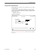


Table Of Contents
- Contents
- About This Guide
- About the FrameSaver DSL Unit
- User Interface and Basic Operation
- Configuration Procedures
- Configuration Options
- Overview
- Using the Easy Install Feature
- Setting Up So the Router Can Receive RIP
- Entering System Information and Setting the System Clock
- Configuration Option Tables
- Configuring the Overall System
- Configuring the Physical Interfaces
- Configuring Frame Relay for the Data Port
- Configuring ATM for the Network Interface
- Configuring Circuit and DLCI Records
- Configuring PVC Connections
- Setting Up Management and Communication Options
- Configuring Node IP Information
- Configuring Management PVCs
- Configuring General SNMP Management
- Configuring Telnet and/or FTP Session Support
- Configuring SNMP NMS Security
- Configuring SNMP Traps
- Configuring the Ethernet Port
- Configuring the Communication Port
- Configuring the COM Port to Support an External Modem
- Security and Logins
- Operation and Maintenance
- FTP Operation
- Troubleshooting
- Setting Up OpenLane for FrameSaver Devices
- Setting Up Network Health for FrameSaver Devices
- Menu Hierarchy
- SNMP MIBs and Traps, and RMON Alarm Defaults
- Connectors, Cables, and Pin Assignments
- Technical Specifications
- Equipment List
- Index

Configuration Options
4-4
9783-A2-GB20-00
July 2000
Table 4-1. Easy Install Configuration Options (1 of 2)
Node IP Address
Possible Settings: 001.000.000.000 – 223.255.255.255, Clear
Default Setting: Clear (000.000.000.000)
Specifies the IP address needed to access the node. Since an IP address is not bound
to a particular port, it can be used for remote access via a management PVC.
001.000.000.000 – 223.255.255.255 – Shows the IP address for the node, which can be
viewed or edited.
Clear – Fills the node IP address with zeros.
Node Subnet Mask
Possible Settings: 000.000.000.000 – 255.255.255.255, Clear
Default Setting: 000.000.000.000
Specifies the subnet mask needed to access the node. Since the subnet mask is not
bound to a particular port, it can be used for remote access via a management PVC.
000.000.000.000 – 255.255.255.255 – Shows the subnet mask for the node, which can
be viewed or edited.
Clear – Fills the node subnet mask with zeros. When the node’s subnet mask is
all zeros, the IP protocol creates a default subnet mask based upon the class of the
IP address: Class A: 255.000.000.000, Class B: 255.255.000.000, or Class C:
255.255.255.000.
TS Access (Type)
Possible Settings: None, VPI,VCI, DLCI_on_VPI,VCI
Default Setting: VPI,VCI
Specifies whether a DLCI or Virtual Circuit (VC) is defined for troubleshooting by the
service provider.
None – No troubleshooting link is defined.
VPI,VCI – A troubleshooting VC is defined. Its identifiers must be entered in the next
field.
DLCI_on_VPI,VCI – A DLCI is defined on a specified VC. The identifiers must be
entered in the following fields.
TS Access (DLCI)
Possible Settings: 16–1007
Default Setting: blank
Specifies the DLCI on the network interface to be used for troubleshooting by the
service provider.
Display Conditions
– This option only appears when TS Access type is
DLCI_on_VPI,VCI.
16 – 1007 – Specifies the DLCI.
TS Access (VPI)
Possible Settings: 0–15
Default Setting: 0
Specifies the VPI on the network interface to be used for troubleshooting by the service
provider. VPI 0, VCI 35 is the default management path between the FrameSaver DSL
unit and the Hotwire GranDSLAM.
0 – 15 – Specifies the VPI.