
User's Manual
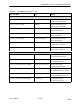
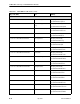

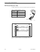
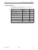
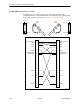

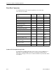
Table Of Contents
- Contents
- About This Guide
- About the FrameSaver DSL Unit
- User Interface and Basic Operation
- Configuration Procedures
- Configuration Options
- Overview
- Using the Easy Install Feature
- Setting Up So the Router Can Receive RIP
- Entering System Information and Setting the System Clock
- Configuration Option Tables
- Configuring the Overall System
- Configuring the Physical Interfaces
- Configuring Frame Relay for the Data Port
- Configuring ATM for the Network Interface
- Configuring Circuit and DLCI Records
- Configuring PVC Connections
- Setting Up Management and Communication Options
- Configuring Node IP Information
- Configuring Management PVCs
- Configuring General SNMP Management
- Configuring Telnet and/or FTP Session Support
- Configuring SNMP NMS Security
- Configuring SNMP Traps
- Configuring the Ethernet Port
- Configuring the Communication Port
- Configuring the COM Port to Support an External Modem
- Security and Logins
- Operation and Maintenance
- FTP Operation
- Troubleshooting
- Setting Up OpenLane for FrameSaver Devices
- Setting Up Network Health for FrameSaver Devices
- Menu Hierarchy
- SNMP MIBs and Traps, and RMON Alarm Defaults
- Connectors, Cables, and Pin Assignments
- Technical Specifications
- Equipment List
- Index
Connectors, Cables, and Pin Assignments
C-3
9783-A2-GB20-00
July 2000
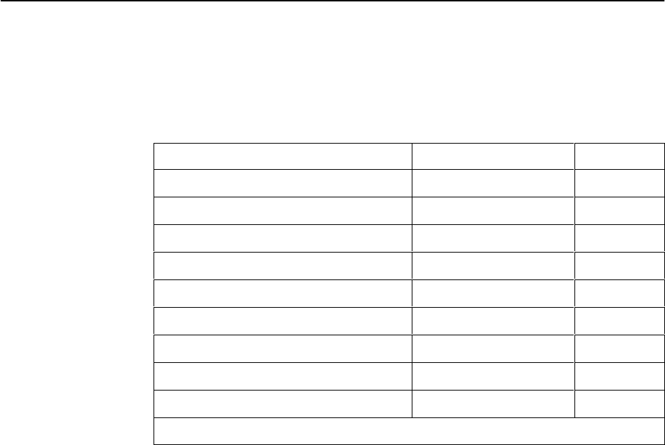
COM Port Connector
The following table provides the pin assignments for the FrameSaver unit’s
25-position EIA-232C communication port connector.
Signal
Direction Pin #
Shield (GND) — 1
DCE Transmit Data (TXD) From DTE (In) 2
DCE Receive Data (RXD) To DTE (Out) 3
DCE Request To Send (RTS) From DTE (In) 4
DCE Clear To Send (CTS) To DTE (Out) 5 *
DCE Data Set Ready (DSR) From DTE (In) 6 *
Signal Ground (GND) — 7
DCE Carrier Detect (CD) To DTE (Out) 8 *
DCE Data Terminal Ready (DTR) From DTE (In) 20
* Pins 5, 6, and 8 are tied together.