
User's Manual

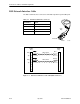
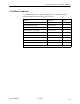
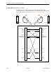

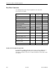

Table Of Contents
- Contents
- About This Guide
- About the FrameSaver DSL Unit
- User Interface and Basic Operation
- Configuration Procedures
- Configuration Options
- Overview
- Using the Easy Install Feature
- Setting Up So the Router Can Receive RIP
- Entering System Information and Setting the System Clock
- Configuration Option Tables
- Configuring the Overall System
- Configuring the Physical Interfaces
- Configuring Frame Relay for the Data Port
- Configuring ATM for the Network Interface
- Configuring Circuit and DLCI Records
- Configuring PVC Connections
- Setting Up Management and Communication Options
- Configuring Node IP Information
- Configuring Management PVCs
- Configuring General SNMP Management
- Configuring Telnet and/or FTP Session Support
- Configuring SNMP NMS Security
- Configuring SNMP Traps
- Configuring the Ethernet Port
- Configuring the Communication Port
- Configuring the COM Port to Support an External Modem
- Security and Logins
- Operation and Maintenance
- FTP Operation
- Troubleshooting
- Setting Up OpenLane for FrameSaver Devices
- Setting Up Network Health for FrameSaver Devices
- Menu Hierarchy
- SNMP MIBs and Traps, and RMON Alarm Defaults
- Connectors, Cables, and Pin Assignments
- Technical Specifications
- Equipment List
- Index
Connectors, Cables, and Pin Assignments
C-2
9783-A2-GB20-00July 2000
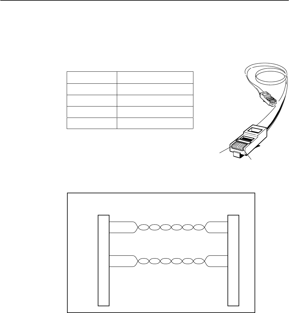
DSL Network Interface Cable
The DSL network interface connector is an RJ48C 8-position keyed modular jack.
Table J-1. DSL Network Interface Connector
Pin Number
Signal
1 (Unused)
2 (Unused)
4 Ring
5 Tip
98-15954a
Ring
Tip
Ring
Tip
Twisted Pair
Twisted Pair
RJ48C
Plug
1
2
3
4
5
6
7
8
RJ48C
Plug
1
2
3
4
5
6
7
8
Blue
White
Orange
White
Blue
White
Orange
White
Blue
White
Orange
White
Blue
White
Orange
White
Blue
White
Orange
White
Blue
White
Orange
White
Blue
White
Orange
White
Blue
White
Orange
White
Blue
White
Orange
White
Blue
White
Orange
White
Figure C-1. DSL Network Interface Cable with RJ48C Connector )
97-15884
8-Pin
Plug
Pin #1
Pin #8