
User's Manual
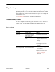
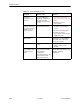

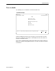


Table Of Contents
- Contents
- About This Guide
- About the FrameSaver DSL Unit
- User Interface and Basic Operation
- Configuration Procedures
- Configuration Options
- Overview
- Using the Easy Install Feature
- Setting Up So the Router Can Receive RIP
- Entering System Information and Setting the System Clock
- Configuration Option Tables
- Configuring the Overall System
- Configuring the Physical Interfaces
- Configuring Frame Relay for the Data Port
- Configuring ATM for the Network Interface
- Configuring Circuit and DLCI Records
- Configuring PVC Connections
- Setting Up Management and Communication Options
- Configuring Node IP Information
- Configuring Management PVCs
- Configuring General SNMP Management
- Configuring Telnet and/or FTP Session Support
- Configuring SNMP NMS Security
- Configuring SNMP Traps
- Configuring the Ethernet Port
- Configuring the Communication Port
- Configuring the COM Port to Support an External Modem
- Security and Logins
- Operation and Maintenance
- FTP Operation
- Troubleshooting
- Setting Up OpenLane for FrameSaver Devices
- Setting Up Network Health for FrameSaver Devices
- Menu Hierarchy
- SNMP MIBs and Traps, and RMON Alarm Defaults
- Connectors, Cables, and Pin Assignments
- Technical Specifications
- Equipment List
- Index

Troubleshooting
8-11
9783-A2-GB20-00
July 2000
Trap Event Log
The Trap Event Log displays all traps stored in the SNMP trap event log. The
following log example describes the alarm conditions that will generate an SNMP
trap for a physical interface, and for the frame relay LMIs and DLCIs. These
alarm conditions also generate Health and Status messages seen on the System
and Test Status screen.
See
Trap Event Log
in Chapter 6,
Operation and Maintenance
.
Troubleshooting Tables
The unit is designed to provide many years of trouble-free service. However, if a
problem occurs, refer to the appropriate table in the following sections for
possible solutions.
Device Problems
Table 8-2. Device Problems (1 of 2)
Symptom
Possible Cause Solutions
No power, or the LEDs
are not lit.
The power cord is not
securely plugged into the
wall receptacle to rear
panel connection.
Check that the power cord is
securely attached at both ends.
The wall receptacle has no
power.
H Check the wall receptacle
power by plugging in some
equipment that is known to be
working.
H Check the circuit breaker.
H Verify that your site is not on
an energy management
program.
Power-On Self-Test
fails. Only Alarm LED
is on after power-on.
The unit has detected an
internal hardware failure.
H Reset the unit and try again.
H Contact your service
representative.
H Return the unit to the factory
(refer to
Warranty, Sales,
Service, and Training
Information
on page A of this
document).